background image

RCS                                                                                                                User Manual 


81 


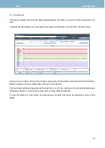
Once you select the zone, click the 

“Search” button again. So you can see the alarms generated in 

the new time frame. If the number of alarms generated is high, you will see a summary in the table 
at  the  bottom  of  the  window.  But  if  the  number  of  alarms  is  small,  you  can  see  the  detailed 
information of all the alarms: 


At the bottom of the screen, you can see the details of each alarm generated in this period: 

Summary of Contents for RCS 100

Page 1: ...RCS 100 RCS 400 Remote monitoring systems Version 11 04 User Manual...

Page 2: ...3 1 1 3 System Info 24 1 2 Input Output 30 1 3 Channel Plans 32 1 3 1 RF Channel Plans 32 1 3 2 ASI 34 1 3 3 IP Channel Plans only for IP inputs option 902518 34 1 4 Utilities 38 1 4 1 DataBase Manage...

Page 3: ...sis 63 4 8 TS Recorder 64 4 9 Quality of Service 65 4 9 1 SLA 66 5 RF Analysis 68 5 1 Measurements 68 5 2 Constellation Option 902511 69 6 Spectrum Option 902511 70 7 Polling 73 7 1 Polling 73 7 2 His...

Page 4: ...RCS User Manual 4...

Page 5: ...ter and Molsture This product is not water resistant Do not use in conditions where condensation may exist The entry of water increases the risk of electric shock Grounding or Polarization Do not bypa...

Page 6: ...quipment near uninsulated power lines or any other hazards Servicing There are no user serviceable parts in this equipment Do not attempt to service this product or remove covers Refer all servicing t...

Page 7: ...400MHz Resolution 100 KHz Tuning Channel and frequency Inputs RCS 100 RCS 400 RF 1 x F 75 connector 4 x F 75 connector ASI 1 x BNC 75 connector 4 x BNC 75 connector IP Option 902518 Dashboard with the...

Page 8: ...Option 902519 Alarm TS Recording Option 902519 RDS Analysis Electronic Program Guide Loudness metering according EBU Tech Doc 3341 Option 902569 Black and Freeze Detection Option 902568 Audio Silence...

Page 9: ...RCS User Manual 9...

Page 10: ...e required for simultaneous TS analysis with main IP Input 902558 PID monitoring and Bitrate monitoring 902564 DVB CI Slot 902568 Black and Freeze and Audio Silence Detection 902569 Loudness metering...

Page 11: ...LCD Display Menu selection buttons Navigation buttons within each menu OK Button Selects the parameter in the submenu Back Button Closes the submenu if open Home Button Return the control of the equi...

Page 12: ...RCS User Manual 12 15 14 Back RF input ASI IN ASI OUT TSoIP Control HDMI USB Power Supply 8 8 9 10 11 14 12 15 9 10 11 8 9 10 11 13 12 15 RCS 100 RCS 400 14 13 12 13...

Page 13: ...CS is shipped in DHCP mode so the IP will be assigned automatically To enter a certain fixed IP press the Setup button and select the STATIC option Then you must enter an IP address within the range o...

Page 14: ...on you must introduce an user name and the corresponding password For the first time you must use the following ones User admin Password rcs Once you have entered in your application you will be able...

Page 15: ...er open the application it will appear the Dashboard sheet selected All the features of the application will be explained bellow Select the input by clicking the corresponding button Access the settin...

Page 16: ...the RCS Network It is possible to set the network parameters manually or using DHCP If you select manual mode you must introduce all the network parameters IP address DNS etc To save the changes you...

Page 17: ...reasing this value more robust the algorithm will be The minimum recommended value is 5 seconds Uniform variation analysis and Small packet analysis These two parameters define the algorithm s behavio...

Page 18: ...only for RCS100 and RCS400 with the option 902568 This parameter is Window size It defines the duration of the window analysis in seconds to detect audio silence If the RCS detects that there is no so...

Page 19: ...e user wants to receive the reports See section 1 2 Input Output It is also possible to generate and send a report of alarms that the user considers critical each time one or more of these critical al...

Page 20: ...ections a General section indicated with it is applied to all the RCS b Individual section indicated with rcs_serial_number it is applied only to the RCS with that serial number This section takes pre...

Page 21: ...ormat is yyyy mm dd HH MM licensesdir directory location in which all licenses files are stored Each RCS will search its license file in this location Licenses file name must have one of the following...

Page 22: ...periodic time interval of queries to the server FTP server configuration If you select a web server you must configure the following parameters in your RCS FTP Server it is the URL to access the RCSc...

Page 23: ...e has been no error The system checks that everything is correct and if so enables the Add button When you click this button the new user will be registered To delete a user you must click the Delete...

Page 24: ...the last reboot You can see more information by clicking on Extended Info button Warning There may be up to 8 users connected to a particular RCS at the same time Administrators can disconnect other u...

Page 25: ...See section Description of Equipment Components If the RCS finds no USB flash drive then it will try to connect to our server via internet to check the latest firmware version available This is possi...

Page 26: ...RCS User Manual 26 2 In such a case click on the UPDATE button 3 A bar will show the updating progress...

Page 27: ...NISHED Update successful The system is going to reboot NOTE Browsers use to store in an own cache the last webs visited After the update some browsers could show an old web stored in cache instead of...

Page 28: ...RCS User Manual 28 Below it will be explained the steps you must follow to erase the browser cache for Google Chrome web browser 1 Choose Configuration 2 Click on Advanced options...

Page 29: ...RCS User Manual 29 3 Choose Clear browsing data 4 Select all the checkboxes and select beginning of time on the menu at the top Then click Clear browsing data 5 Close browser and open it again...

Page 30: ...t the signal is not locked The blue color indicates that the input is enabled the signal is locked and operating in polling mode The yellow color indicates that the input is enabled the signal is lock...

Page 31: ...4 different satellites The user must select the channel plan for each DiSEqC command A B C D as well as the Vcc If OFF is selected it is only necessary to select the channel plan of the input Outputs...

Page 32: ...ght side The plan that you choose will be used in all the features You can delete the selected plan or export it to a CSV file To edit a RF channel plan you must export it to a CSV file make the chang...

Page 33: ...s these are the profiles assigned by default to all the channels of the plan If the RCS has not user_selection profiles then the profiles assigned by default are the Factory default ones You can also...

Page 34: ...sign the factory default profiles to all the channels To do that please press the Restore Factory Default Profiles If you want to assign the same profiles to all the channels please press the Bulk Con...

Page 35: ...el plan Delete Deletes the selected channel plan Note the active channel plan can not be deleted Export Exports the selected channel plan to a CSV file The alarms profiles won t be exported to the CSV...

Page 36: ...IP alarms profile assigned to the channel ETR290 is the ETR290 alarms profile assigned to the channel SERVICES is the services alarms profile assigned to the channel PID is the PID Blacklist alarms pr...

Page 37: ...sponding field of the channel TSoIP1 TSoIP2 will use this IP address So the same VLAN can t be assigned to both network interfaces The channel features are explained below Save Changes Saves the chang...

Page 38: ...he memory reserved for it the oldest files will be automatically removed to free memory to save the new alarms If you select Save Services Information ON id addition to measurements and alarms the ser...

Page 39: ...he data you want to restore you must enter the configuration file name and click the Send button The data will be loaded and the RCS will be configured automatically 1 4 3 Cloning This feature allows...

Page 40: ...is a list of PID that the user wants to ignore that is the alarms generated in the PID included in the Blacklist will not be activated so the user will not see them You can configure as many alarms p...

Page 41: ...ordings See section 3A 7 TS Recorder The name of the recordings corresponding to alarm events includes the name of the alarm Active User can activate or deactivate each alarm and set the parameters fo...

Page 42: ...u can see in the image above there are 3 parameters to configure in addition to the measurement threshold Time ON Time OFF and N num The system generates an alarm on message when the alarm is out of t...

Page 43: ...generate the alarm off message The alarm on message is generated when the measurement get out of the threshold Ton N 3 Alarm on Alarms off Ton Measurement threshold Time axis Toff During the Time ON p...

Page 44: ...ted alarm warning Once the measurement is back within the thresholds the alarm off message is generated immediately The PID bitrates alarms profiles must be explained separately The user must indicate...

Page 45: ...time N is the number of windows of time and t is the duration of each window of time The size of the elements refers to the bytes taken into account 188 is the total number of bytes and payload are th...

Page 46: ...can easily see the profiles assigned to the selected channel from any measurements window clicking on the Profiles button at the top bar of the window Then a popup window will be open showing all the...

Page 47: ...ction 3 All in One or 6 RF Analysis or in spectrum mode see section 7 Spectrum If it is in continuous or spectrum mode it also shows the name and the frequency of the tuned channel If it is in polling...

Page 48: ...RCS User Manual 48 For ASI inputs each card indicates if the signal is locked the bitrate the number of services and the alarms...

Page 49: ...only available if RF input is selected Span 20 MHz and reference selected automatically according to the signal Distribution of transport services and the bitrate of each one Mosaic with the screensho...

Page 50: ...e Alarms section in detail Alarms summary in the top part you can see a summary that shows the number of alarms of each type as well as a colored circle The colors of the circles are explained below G...

Page 51: ...ist so you can check a particular alarm Services section Following you can see the Services section in detail As you can see there is a graph representing the distribution of transport services and th...

Page 52: ...color the mean loudness value must be in the dark blue zone The user can enable the alarm corresponding to the loudness measurement included in the type of alarm Service see section 1 5 1 Alarms profi...

Page 53: ...ements for RCS100 y RCS400 Power C N MER CBER VBER Left shoulder Right shoulder and Frequency offset option 902529 for RCS50 Power C N MER CBER VBER and the signal parameters The colors of the bars ar...

Page 54: ...yellow triangle in the top of the window indicates that there are some channels in the plan in more than one input These channels will be locked only in the first input Edit button Goes to IP channel...

Page 55: ...ected IP frames It is the number of corrected wrong packets For all the inputs if your RCS has the option 902564 and the CI card is placed in the slot see section Description of Equipment Components t...

Page 56: ...RCS User Manual 56 If you click on the CI card icon see image above a popup window will be open to show the card information...

Page 57: ...color in the time period selected by the user from the dropdown that appears just below the graph Below the chart there is a list of all the channel services with their corresponding bitrates The col...

Page 58: ...ervices of the selected channel and the time elapsed interval between two consecutive receptions of the table for each one as well as the maximum and minimum values of the measured interval elapsed si...

Page 59: ...User Manual 59 Placing the mouse over one of the events a popup window will be shown displaying the information about that event You can also click on the event to see further more information about...

Page 60: ...lity of PCR timestamps A high jitter may cause the decoder is unable to reconstruct the clock correctly and so the video may not decoded properly The standard indicates that jitter must be less than 5...

Page 61: ...tree where the service ID and the name is displayed besides By expanding a node they are shown all the packets of the service with the ID of each one and the information about the packet type And when...

Page 62: ...displayed next to the video audio icon a lock indicates that the service is encrypted and an E even or an O odd indicating the scramble status 4 6 Service Monitoring Option 902558 This feature allows...

Page 63: ...at the same time You can create up to ten different templates for the same service When the configuration of a monitored service does not correspond with any of the templates a service monitoring alar...

Page 64: ...the next event The recording duration depends on the bitrate of the transport stream and the available space in the memory you can store several recordings Bellow the buttons there is a bar graph tha...

Page 65: ...will be shown Service Availability Error Ratio Service Degradation Error Ratio Service Impairments Error Ratio These rates give an idea of the rate of time the corresponding alarm is active Qos repor...

Page 66: ...ive during the configured timeslot in the SLA settings Last Window Percentage of time with some alarm active during the entire measurement of the last slot configured in the SLA settings Last 24 hours...

Page 67: ...ent has been turned on to the current one and the tittle will indicate as Incomplete When the Service Quality history is checked the SLA one will be also available as follows SLA Summary Summary of th...

Page 68: ...ments In this window you can see a graph with the evolution of the measurements in a time interval selected by the user The measurements shown are Power C N MER CBER and VBER The colors of the bars ar...

Page 69: ...eal time The measurements shown are Power C N MER CBER VBER Left shoulder Right shoulder and Frequency offset opt 902529 The colors of the bars are related to the alarms thresholds Circles colors matc...

Page 70: ...d using the keyboard Marks As you can see in the image above there are two markers in the spectrum that the user can move to see the signal level in a particular frequency The measurements correspondi...

Page 71: ...marks in the graph Export spectrum as PNG Allows exporting the spectrum image as a PNG file Mask options The user can also define a mask pressing the button New Mask and selecting the minimum and max...

Page 72: ...of the selected mask Or you can load a mask to the spectrum graph by clicking on the Load mask button of the corresponding mask At the bottom of the window all alarms for the tuned channel are shown a...

Page 73: ...is selected a RF input the polling window looks like this On the right side of the window there is a bar graph of power measurement The colors of the bars depend on the alarms if a cannel has an acti...

Page 74: ...splayed In the right side of the screen there is a list with the IP real time measurements of the channel that is being measured as well as the bitrates of the channel In the center of the window ther...

Page 75: ...istorical Pollings This feature allows you to visualize all the measurements made by your RCS with the polling function Each list of measurements is identified with the date and time of the start of p...

Page 76: ...on is activated in the DB management menu and another with information about the equipment and the entry from which the data was obtained 7 3 Configuration Using this feature the user can configure al...

Page 77: ...easuring time is the time during wich the RCS makes the measurements and generates the alarms in each channel Once the time has elapsed the RCS tunes the next channel In the channel selection table th...

Page 78: ...he measurements and generates the alarms in each channel Once the time has elapsed the RCS tunes the next channel In the channel selection table the user can select the channels he wants to include in...

Page 79: ...The data shown in the graph can be filtered by several parameters using the buttons placed on the right side of the window On the bottom of the window there is a table with the latest alarms generate...

Page 80: ...utton As you can see above the window shows a graph with all the alarms generated in that time frame Below the graph there is a table with a resume of the alarms You can download the measures and the...

Page 81: ...in the new time frame If the number of alarms generated is high you will see a summary in the table at the bottom of the window But if the number of alarms is small you can see the detailed informatio...

Page 82: ...able a pop up window will show all the alarms of that type indicating the channel where it has occurred Note that the limit of alarms shown in this window is 20000 By clicking on Download data a csv f...

Page 83: ...ault the RCS shipped in DHCP mode so the IP will be selected automatically To enter a certain fixed IP press the Setup button and select the STATIC option Then you must enter an IP address within the...

Page 84: ...information before it shuts down definitively Brightness The user can increase or decrease the brightness of the screen pressing the buttons Home and or at the same time NETWORK IP 192 168 010 164 GW...

Page 85: ...the unit Replacing fuses only for old hardware versions The RCS uses two T1AL 250V crystal 5x20mm fuses The fuses are placed in the back of the equipment on the right side See section Description of...

Page 86: ...RCS User Manual 86 Then you can now connect the power connector and make sure that you equipment works properly...

Page 87: ...hout first contacting Gsertel Technical Support If the unit needs to be returned Gsertel will arrange for free shipping The unit will need to be appropritely packed for shipping In compliance with IAT...

Page 88: ...ed Keep the purchase invoice to determine this date During the guarantee period Gsertel becomes position of the failures produced by defect of the material or manufacture The harm produced by improper...

Reviews: