11. Drive Motor and Motor Mount
PNEG-681CE
CE Compliant Series II Bucket Elevator
39
Drive Guard
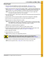
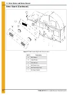
1. Attach the drive guard brackets to the motor mount assembly.
The shorter, broken legs of the brackets will point towards the pulley.
2. Align the guard rear panel of the guard to the brackets. NOTE, in a right hand drive application (as
) the flanges of the guard rear panel will face away from
the head section, but in a left hand application, the flanges will point towards the head section.
NOTE:
The wider, larger hole in the guard rear panel is intended for the motor output shaft.
The guard rear panel will attach only in one orientation.
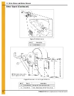
3. Once rear panel is bolted on, attach the drive guard struts to the bearing support of the head section
and to the rear panel.
4. Using hardware, bolt the two (2) struts together. All brackets are designed to be adjustable.
5. Place sheaves onto the output shaft of the motor and the input shaft of the reducer.
6. Place belts upon the sheaves and tension as needed.
NOTE:
Reducer may need to be rotated, clockwise or counterclockwise, in conjunction with slide
base adjustments, to achieve correct center distance for the drive belts. Move the location
of the reducer torque arm turnbuckle to achieve this rotation, as needed.
NOTE:
Belts are designed specifically per application.
7. With drive belts tensioned and reducer rotated (if necessary), tighten all bolts.
8. Install the safety screen around the motor output shaft by approximating the hole location to the
screen and snipping a clearance hole in screen.
9. Attach using proper hardware.
10. Attach belt guard cover, latch and bolt.
NOTE:
Shaft mount reducers are shipped without lubricant.
11. With the reducer in vertical position, fill with lubricant until oil runs out of oil level plug.
NOTE:
See the Appendix section
for volume of oil per reducer size.
CAUTION
NEVER operate the elevator until the gear reducer has been filled with an
approved lubricant as noted in the Torque Arm II Appendix section
.


