background image

6", 8", and 10"                                          
Bin Sweep Auger

Installation & Operation Manual

PNEG-1020

Date: 02-10-07

Summary of Contents for PNEG-1020

Page 1: ...6 8 and 10 Bin Sweep Auger Installation Operation Manual PNEG 1020 Date 02 10 07...

Page 2: ...2 PNEG 1020 Bin Sweep Auger...

Page 3: ...Flighting to the Shield 18 Wheel Assembly 18 Install the Motor Mount Rods 19 Install the Pivot Pin Extension If needed 20 Install the Bin Sweep into the Bin 20 Chapter 5 10 Bin Sweep Assembly Install...

Page 4: ...1 Parts List 35 6 Bin Sweep Auger 36 8 Bin Sweep Auger 40 10 Bin Sweep Auger 44 6 8 and 10 Bin Sweep Auger Wheel Assembly 46 Chapter 12 Warranty 47 Personnel operating or working around this equipment...

Page 5: ...nal information or assistance should be required please contact your dealer or the manufacturer 3 It is important to check both the quantity of parts and their descriptions with the packing list enclo...

Page 6: ...this is the type of motor being used use only those with a manual reset 2 The motor starting controls must be located outside the bin They must NEVER be installed on the Bin Sweep Auger inside the bin...

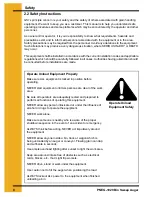
Page 7: ...suse of the equipment and may lead to serious injury or death This is the safety alert symbol It is used to alert you to potential personal injury hazards Obey all safety messages that follow this sym...

Page 8: ...fore installations are made Operate Unload Equipment Properly Make sure ALL equipment is locked in position before operating NEVER start equipment until ALL persons are clear of the work area Be sure...

Page 9: ...t of this manual and need assistance contact your dealer Read and Understand Manual Install Operate Electrical Equipment Properly To avoid serious injury or death stay away from unit and make sure eve...

Page 10: ...safety equipment appropriate to the job Safety glasses should be worn at all times to protect eyes from debris Wear gloves to protect your hands from sharp edges on plastic or steel parts Wear steel t...

Page 11: ...ional Safety Health Administration regulations state At the time of initial assignment and at least annually thereafter the employer shall instruct every employee in the safe operation and servicing o...

Page 12: ...appear on the auger Note Please remember safety signs provide important safety information for people working near bin unloading equipment that is in operation Any safety signs that are worn missing...

Page 13: ...ment in the area or any reason then locate the safety sign in a more suitable location 4 Be certain the surface is clean dry and free of dirt and oil Peel paper backing from decals and stick into plac...

Page 14: ...nd nuts Figure 4 1 A Figure 4 1 B 2 Tighten the carriage bolts and nuts Figure 4 1 C 3 Place a lock collar onto the shaft Do not tighten 4 Place the motor mount assembly onto the shaft making sure tha...

Page 15: ...ey is facing inward toward the motor mount assembly Figure 4 2 A 2 Turn the pulley wheel so that the roll pin hole on the pulley shaft and the roll pin hole on the tube align Figure 4 2 B 3 Insert a 5...

Page 16: ...osest to the pulley counter clockwise until tight noted in Figure 4 3 B Then proceed to tighten with an 1 8 hex head wrench shown in Figure 4 3 C Figure 4 3 B Figure 4 3 C 4 4 Install the Shield Suppo...

Page 17: ...e torque tube brackets onto the torque tube Do not tighten completely Figure 4 5 B 4 6 Install the Shield 1 Position the torque tube clamp underneath the shield Align holes in torque tube clamps with...

Page 18: ...to the shield using four 4 5 16 x 1 bolts washers and nuts for each area as shown in Figure 4 8 B Figure 4 8 B Note Make sure to place the head of the bolts on the inside of the shield with the thread...

Page 19: ...cs onto the shaft followed by five 5 rubber discs followed by two 2 steel disc Figure 4 9 C 4 When finished the wheel assembly should appear as shown Figure 4 9 D 5 Place one 1 3 4 lock washer and one...

Page 20: ...e motor mount assembly Figure 4 11 A 4 12 Install the Bin Sweep into the Bin 1 After removing all grain from the center well and intermediate well place the bin sweep auger in the bin 2 Place the pin...

Page 21: ...Figure 5 1 B 2 Tighten the carriage bolts and nuts Figure 5 1 C 3 Place a lock collar onto the shaft Do not tighten 4 Place the motor mount assembly onto the shaft of the small flighting section makin...

Page 22: ...the pulley is facing inward toward the motor mount assembly Figure 5 2 A 2 Turn the pulley wheel so that the roll pin hole on the pulley shaft and the roll pin hole on the tube align Figure 5 2 B 3 In...

Page 23: ...to the pulley counter clockwise until tight noted in Figure 5 3 B Then proceed to tighten with an 1 8 hex head wrench shown in Figure 5 3 C Figure 5 3 B Figure 5 3 C 5 4 Install the Flighting 1 Insert...

Page 24: ...nuts Figure 5 6 A 5 7 Install the Flighting Shield 1 Install the smallest shield to the shield mounting bracket located on the motor mount assembly Secure using two 2 3 8 x 3 bolts and lock nuts Make...

Page 25: ...h Figure 5 8 A 5 9 Install the Hanger Bearing Bracket 1 Place the hanger bearing bracket onto the wheel shaft Figure 5 9 A 5 10 Install the Wheel Shaft 1 Slide the wheel shaft into the flighting Secur...

Page 26: ...a two 2 3 8 x 2 1 2 carriage bolt lock washer and nut Figure 5 11 B 3 Insert the threaded ends of the motor mount rods into the motor mount The motor mount rods should be facing away from the pulley a...

Page 27: ...ace the pin located on the sweep motor mount into the tube provided on top of the well 3 Lay the sweep auger on the pile of sloping grain 4 Use the extension tube between the motor mount and the bin w...

Page 28: ...roblems 4 Be aware of any emergency shutdown procedures Two 2 people must always be in a position where the operation of the equipment can be monitored 5 Before starting the auger for the first time m...

Page 29: ...of time will cause excessive wear NEVER operator the auger at speeds higher than recommended Auger flight speed in excess of recommended speed causes excessive wear Be aware of any unusual vibration o...

Page 30: ...n is empty 3 Remove the sweep auger from the bin before refilling the bin Note The shield must be adjusted to clear the floor at a minimum of 1 2 to allow the sweep wheel to move the sweep properly in...

Page 31: ...while it is under load NEVER start the equipment under load Doing so may cause damage This type of damage is considered a misuse of the equipment Any misuse of the equipment may void the warranty 3 C...

Page 32: ...our dealer or the manufacturer 3 Ensure that ALL electric motors etc are operating at the proper speed 4 Maintain proper adjustments on the belt s 5 Mount controls for any electric motors at a safe di...

Page 33: ...ion 2 Auger plugs 1 Excessive drag 1 Check the clearance between the shield and the bin floor for excessive drag Adjust the shield and carriers to clear metal floor splices or cracks in concrete floor...

Page 34: ...34 PNEG 1020 Bin Sweep Auger NOTES...

Page 35: ...PNEG 1020 Bin Sweep Auger 35 Parts List 11 PARTS LIST 6 Bin Sweep Auger 8 Bin Sweep Auger 10 Bin Sweep Auger 6 8 and 10 Bin Sweep Auger Wheel Assembly...

Page 36: ...36 PNEG 1020 Bin Sweep Auger Parts List 6 Bin Sweep Auger A center bushing is welded in the center of two lengths of flighting connecting them together on sweeps for bins larger than 29 in diameter...

Page 37: ...Bearing Clamp Bracket 9 GK1078 15 36 2 Pair Torque Tube Clamp 10 GK1075 15 36 1 Shield Support Bracket 11 GK1079 15 1 Shield 76 long GK1084 18 1 Shield 94 long GK1071 21 1 Shield 112 long GK1091 24 1...

Page 38: ...38 PNEG 1020 Bin Sweep Auger Parts List 6 Bin Sweep Auger A center bushing is welded in the center of two lengths of flighting connecting them together on sweeps for bins larger than 29 in diameter...

Page 39: ...2 long GK1244 21 1 Flighting 120 long GK1246 24 1 Flighting 138 long GK1248 27 1 Flighting 156 long GK1251 30 1 Flighting 174 long GK1252 33 1 Flighting 192 long GK1254 36 1 Flighting 210 long 14 GK13...

Page 40: ...40 PNEG 1020 Bin Sweep Auger Parts List 8 Bin Sweep Auger A center bushing is welded in the center of two lengths of flighting connecting them together on sweeps for bins larger than 29 in diameter...

Page 41: ...n Tube 8 GK1074 15 36 1 Pair Bearing Clamp Bracket 9 GK1078 15 36 2 Pair Torque Tube Clamp 10 GK1075 15 36 1 Shield Support Bracket 11 GK1079 15 1 Shield 76 long GK1084 18 1 Shield 94 long GK1071 21 1...

Page 42: ...42 PNEG 1020 Bin Sweep Auger Parts List 8 Bin Sweep Auger A center bushing is welded in the center of two lengths of flighting connecting them together on sweeps for bins larger than 29 in diameter...

Page 43: ...long GK1089 21 1 Flighting 120 long GK1093 24 1 Flighting 138 long GK1097 27 1 Flighting 156 long GK1258 30 1 Flighting 174 long GK1271 33 1 Flighting 210 long GK1275 36 1 Flighting 210 long 14 GK131...

Page 44: ...44 PNEG 1020 Bin Sweep Auger Parts List 10 Bin Sweep Auger A center bushing is welded in the center of two lengths of flighting connecting them together on sweeps for bins larger than 29 in diameter...

Page 45: ...n page 45 See Table in page 45 Shield 6 9 long GK1968 See Table in page 45 See Table in page 45 Shield 8 3 long GK1965 See Table in page 45 See Table in page 45 Shield 9 9 long 9 GK1956 See Table in p...

Page 46: ...38 5 5 OD Rubber Disc Wheel for the 6 Bin Sweep Auger Gk1067 5 6 OD Rubber Disc Wheel for the 8 Bin Sweep Auger GK1671 5 8 OD Rubber Disc Wheel for the 10 Bin Sweep Auger 3 Gk1232 4 4 OD Steel Wheel D...

Page 47: ...HALL NOT BE LIABLE FOR ANY DIRECT INDIRECT INCIDENTAL OR CONSEQUENTIAL DAMAGES INCLUDING WITHOUT LIMITATION LOSS OF ANTICIPATED PROFITS OR BENEFITS PURCHASER S SOLE AND EXCLUSIVE REMEDY IS AS SET FORT...

Page 48: ...nt Installation Codes And Applicable Regulations Which Should Be Carefully Followed In All Cases Authorities Having Jurisdiction Should Be Consulted Before Installations occurs The GSI Group Inc 1004...

Reviews: