INSTALLATION
24
PNEG-1521
Commercial Direct Gear Drive Bin Sweep Auger
9. CLUTCH CONTROL INSTALLATION
(Cont.)
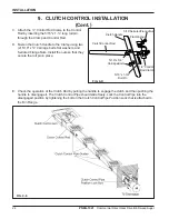
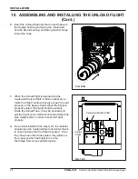
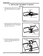
C. Attach the ½” Control Rod Clamp to the Control
Rod by inserting the 5/16" x 1-¾” long roll pin
through the Clamp and Control Rod.
D. Fasten the Clutch Handle to the Clamp using two
(2) 5/16" x ¾” Carriage bolts, flat washers, and
Serrated Flange Nuts. Install the nuts so that they
secure the roll pin in place.
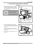
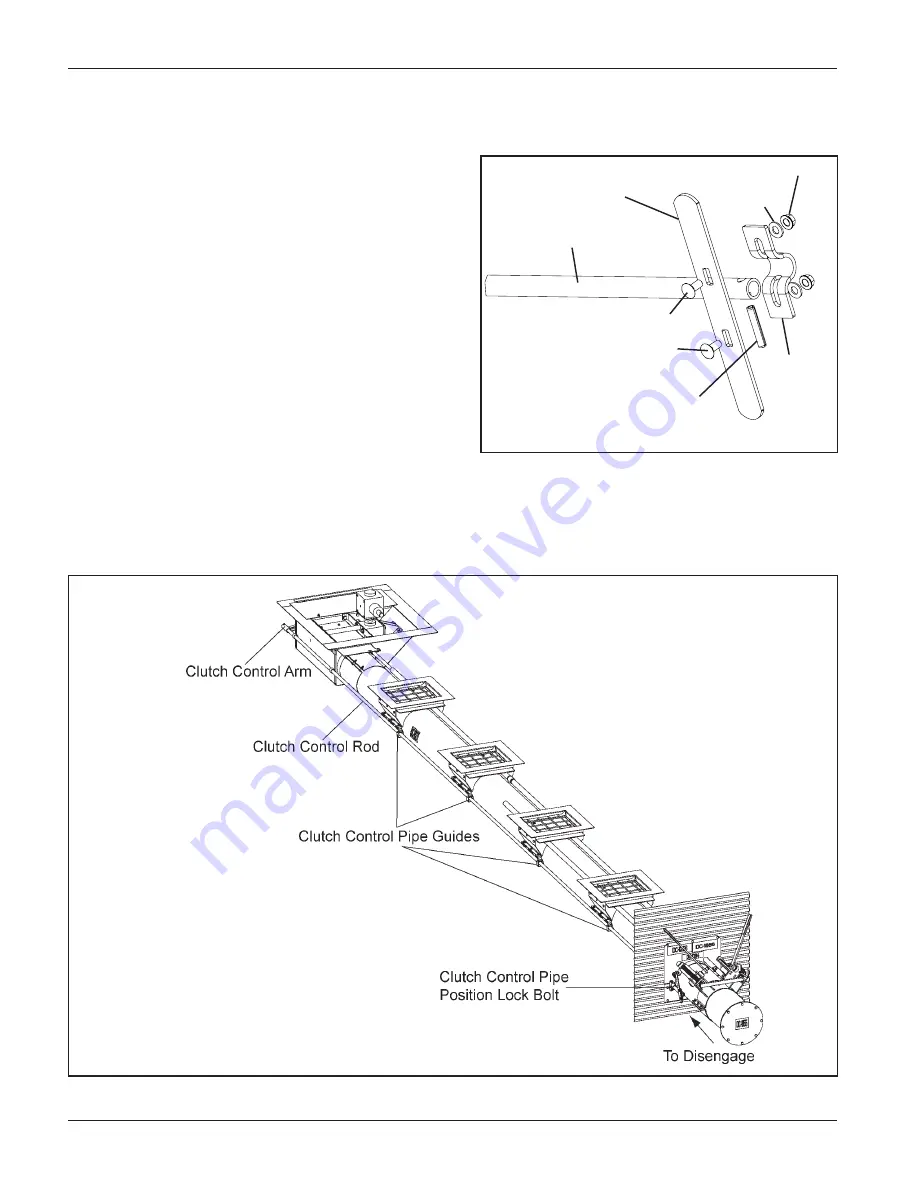
E. Check the operation of the Clutch Rod by pulling the handle to engage the clutch and then pushing the
handle to disengage it. The Clutch Control Pipe should slide freely. Lock the Control Pipe into the
disengaged position by tightening the bolt on the Clutch Control Pipe Position Lock that is attached to
the Bin Flange.
Clutch Handle
5/16”Serrated Flange Nut
Flat Washer
5/16” x 1-3/4”
Roll Pin
1/2” Control
Rod Clamp
Clutch Control Rod
FIG. 9-D
5/16” x 3/4”
Carriage Bolts
FIG. 9-E


