background image

2. Installation

18

PNEG-1614

 Heavy Duty Bin Stairs and Platform Assembly for 2.66" Corrugated Bin

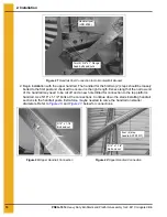
Figure 2T Handrail Post Connection to Horizontal Wall Bracket

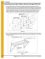
2. Begin installation with the upper handrail. The handrail for the first two (2) steps should be loosely 

bolted to the first post and checked to ensure it is the right length. Excess length of the narrow end 
of the handrail may need to be cut off and a new hole drilled for connection to the top platform 
handrail. Use 5/16" x 1-1/4" bolts at the connections. Continue down the stairs installing handrail 
sections to the handrail posts. Extra force maybe needed to curve the handrail on smaller 
diameters. Refer to 

Figure 2U

 and 

Figure 2V

 below for connections.

Figure 2U Upper Handrail Connection

Figure 2V Upper Handrail Connection

Handrail post 
(LDR-4085)

Two (2) 3/8" x 1" Flange 
head bolts and nuts

5/16" x 1-1/4" 
Bolt and nut

Four (4) step 
handrail (STR1077)

5/16" x 1-1/4" 
Bolt and nut

Summary of Contents for PNEG-1614

Page 1: ...PNEG 1614 Heavy Duty Bin Stairs and Platform Assembly for 2 66 Corrugated Bin Installation Manual PNEG 1614 Date 07 30 09...

Page 2: ...2 PNEG 1614 Heavy Duty Bin Stairs and Platform Assembly for 2 66 Corrugated Bin...

Page 3: ...Chapter 1 Safety 4 Safety Guidelines 4 Safety Instructions 5 Chapter 2 Installation 7 Platform Wall Brackets Stair Wall Brackets and Knee Braces 7 Assembling the Platform 9 Assembling the Stairs 11 A...

Page 4: ...y instructions is a misuse of the equipment and may lead to serious injury or death This is the safety alert symbol It is used to alert you to potential personal injury hazards Obey all safety message...

Page 5: ...e consulted before installations are made Follow Safety Instructions Carefully read all safety messages in this manual and safety signs on your machine Keep signs in good condition Replace missing or...

Page 6: ...ate to the job Remove all jewelry Long hair should be tied up and back Safety glasses should be worn at all times to protect eyes from debris Wear gloves to protect your hands from sharp edges on plas...

Page 7: ...bin one 1 bolt spacing or 9 3 8 NOTE One bolt spacing is the distance between the bolts on the horizontal seams which is equal to 9 3 8 On a 2 66 32 sheet corrugated bin the first ring will contain t...

Page 8: ...m bracket as shown and use 5 16 x 3 4 bin bolts and flange nuts at the top connection points The bottom connection points will also be used for the platform knee brace during platform installation 5 T...

Page 9: ...re at all the connection points Note the center floor brace LS 6701 is offset from the center of the platform The bin wall is hidden for clarity Figure 2D 2 Figure 2E shows the assembly of the platfor...

Page 10: ...tallation 10 PNEG 1614 Heavy Duty Bin Stairs and Platform Assembly for 2 66 Corrugated Bin 3 Figure 2F shows the assembly of the platform handrails These must also be attached using 5 16 hardware Figu...

Page 11: ...rs used on 2 66 corrugated bins The top two 2 stairs are special shorter stairs color coded and shown in Figure 2H The ends of both types of steps are bolted under and behind the step using 5 16 hardw...

Page 12: ...e first vertical wall bracket will be located two 2 bolt spaces or 18 3 4 around the bin 3 8 hardware is used at the four 4 connection points as shown The outer two 2 mounting holes on the side and th...

Page 13: ...are at the connection points and refer to Figure 2L below and Figure 2M Figure 2N and Figure 2O on Page 14 for hole and slot usage for the size bin These illustrations will show how to align the holes...

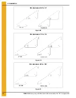
Page 14: ...2 Installation 14 PNEG 1614 Heavy Duty Bin Stairs and Platform Assembly for 2 66 Corrugated Bin Figure 2M Figure 2N Figure 2O Bin diameters 60 to 72 Bin diameters 75 to 78 Bin diameters 90 to 105...

Page 15: ...section The third step attaches to the wall bracket as shown in Figure 2J on Page 12 Use the holes and slots to connect the stairs as shown in the Figure 2L Figure 2M Figure 2N and Figure 2O on Pages...

Page 16: ...d 32 lower and four 4 bolt spaces or 37 1 2 around the bin farther than the previous bracket 6 The last step will need to be supported by a wall bracket assembly It may be necessary to field cut and d...

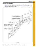
Page 17: ...rrugated Bin 17 Adding the Handrails 1 Figure 2S shows the addition of the handrail posts Use two 2 3 8 x 1 flange bolts and nuts to attach the handrail post to the horizontal wall bracket See Figure...

Page 18: ...f the handrail may need to be cut off and a new hole drilled for connection to the top platform handrail Use 5 16 x 1 1 4 bolts at the connections Continue down the stairs installing handrail sections...

Page 19: ...s and nut See Figure 2S on Page 17 The large tube should be placed on the upper handrail post and the small tube should be slid into it and placed on the lower handrail post The very top intermediate...

Page 20: ...ket should be placed six 6 bolt spaces around the bin at the same height as the previous platform bracket The next stair wall bracket is placed four 4 bolt spaces around the bin and 32 below the secon...

Page 21: ...shows the assembly of the platform floor toe plate and vertical angles This must all be assembled at the same time using 5 16 hardware Note the orientation of the vertical angles Figure 2Z 4 Figure 2...

Page 22: ...late A field drilled 3 8 hole will need to be placed in the handrail in line with the slot in the step Self tapping screws will need to be placed in the top of the step for connection to the toe plate...

Page 23: ...TY FOR A PARTICULAR PURPOSE OR DESIGN OF SUCH PRODUCTS GSI shall not be liable for any direct indirect incidental or consequential damages including without limitation loss of anticipated profits or b...

Page 24: ...regulations which should be carefully followed in all cases Authorities having jurisdiction should be consulted before installations are made GSI Group 1004 E Illinois St Assumption IL 62510 0020 Pho...

Reviews: