Chapter 6 Cutter Compensation
155
I Programming
CHAPTER 6 CUTTER COMPENSATION
6.1 Application for Cutter Radius Compensation
6.1.1 Brief
Generally, the parts machining process is programmed according to parts drawing in one point on a
tool. As for the tool used actually, because of the processing or other requirement, the tool is not an ideal
point, but an arc only. The position offset exists between actual cutting point and ideal point when the
cutting feed is performed. It may cause over cut or undercut, so the part accuracy will be affected. So, the
cutter radius compensation can be used to improve the part accuracy in machining.
The path of part figure can be shifted by a cutter radius, which this method is called B type tool
compensation; this is a simply method but the movement path of next block can be processed only after a
block is performed, so the phenomenon as over cutting will be generated at the intersection point of two
blocks.
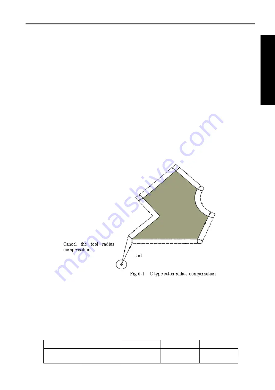
In order to settle the above issues and eliminate the error, the Tool compensation C should be setup.
When a block is read in, the tool compensation C is not performed immediately but the next block is read in
again. Corresponding movement path is calculated according to the point of intersection of two blocks
(conjunction vector). The tool compensation C performs more accurate compensation in figure because two
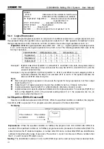
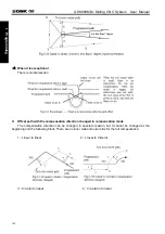
blocks are read for processing in advance. See the Fig. 6-1
6.1.2 Compensation value setting
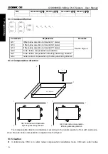
The radius value of each tool should be set before tool compensation C is applied. Tool radius
compensation value is set in the OFFSET page (table 6-1), this page contains tool geometric radius and
tool radius wear. There into, D is the tool compensation value, when the bit 1 of bit parameter No.002 is 1,
the D is compensation value input by diameter. If the bit 1 of bit parameter No.002 is 0, the D is
compensation value input by radius. The following explanations are all indicated in radius compensation
value if not especially pointed out.
Table 6-1 Display page for CNC cutter radius compensation value
NO.
Geometric
(
H
)
Wearing
(
H
)
Geometric
(
D
)
Wearing
(
D
)
001 20.020 0.030 5.000 0.020
002 10.020 0.123 0.500 0.030
Summary of Contents for 980MDc
Page 19: ...GSK980MDc Milling CNC User Manual XVIII ...
Page 20: ...1 I Programming Programming Ⅰ ...
Page 21: ...GSK980MDc Milling CNC System User Manual 2 I Programming ...
Page 139: ...GSK980MDc Milling CNC System User Manual 120 I Programming ...
Page 191: ...GSK980MDc Milling CNC System User Manual 172 I Programming ...
Page 192: ...173 Ⅱ Operation Ⅱ Operation ...
Page 193: ...GSK980MDc Milling CNC System User Manual 174 Ⅱ Operation ...
Page 200: ...Chapter 1 Operation Mode and Display 181 Ⅱ Operation ...
Page 201: ...GSK980MDc Milling CNC System User Manual 182 Ⅱ Operation ...
Page 249: ...GSK980MDc Milling CNC System User Manual 230 Ⅱ Operation ...
Page 253: ...GSK980MDc Milling CNC System User Manual 234 Ⅱ Operation ...
Page 259: ...GSK980MDc Milling CNC System User Manual 240 Ⅱ Operation ...
Page 265: ...GSK980MDc Milling CNC System User Manual 246 Ⅱ Operation ...
Page 293: ...GSK980MDc Milling CNC System User Manual 274 Ⅱ Operation ...
Page 295: ...GSK980MDc Milling CNC System User Manual 276 Ⅱ Operation ...
Page 319: ...GSK980MDc Milling CNC System User Manual 300 Ⅱ Operation ...
Page 320: ...301 Ⅲ Installation Ⅲ Installation ...
Page 321: ...GSK980MDc Milling CNC System User Manual 302 Ⅲ Installation ...
Page 345: ...GSK980MDc Milling CNC System User Manual 326 Ⅲ Installation ...
Page 391: ...GSK980MDc Milling CNC System User Manual 372 Ⅲ Installation ...
Page 392: ...Appendix 373 Appendix Appendix ...
Page 393: ...GSK980MDc Milling CNC System User Manual 374 Appendix ...
Page 394: ...Appendix 375 Appendix Appendix 1 Outline Dimension of GSK980MDc L N ...


