GSK980MDc Milling CNC System User Manual
360
Ⅲ
Inst
allation
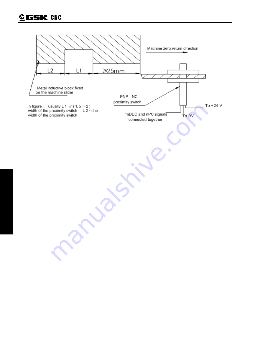
Fig. 4-3
4.6 Spindle Adjustment
4.6.1 Spindle Encoder
Encoder with the linear number 100 p/r ~5000p/r is needed to be installed on the machine for
threading. The linear number is set by data parameter No. 3720. The transmission ratio(spindle gear
teeth/encoder gear teeth) between encoder and spindle is 1/255
~
255. The spindle gear teeth are set
by CNC data parameter No. 3721, and the encoder gear teeth are set by data parameter No. 3722.
Synchronous belt transmission should be applied for it (no sliding transmission).
The DGN.011 and DNG.012 of CNC diagnosis messages are used to check the validity of threading
signal from the spindle encoder.
4.6.2 Spindle Brake
After spindle stop is executed, proper spindle brake time should be set to stop the spindle promptly
in order to enhance the machining efficiency. If the brake is employed with energy consumption type,
too long braking time may damage the motor. So the brake time is set by PLC.
4.6.3 Switch Volume Control of Spindle Speed
When multiple speed motor control is used, motor speed control command can be defined by ladder
diagram as S_ _. Relevant parameter is shown below.
Bit parameter
№
001 ACS=0
:
select switching control of spindle speed.
4.6.4 Analog Voltage Control for Spindle Speed
This function can be obtained by the parameter setting of CNC. By interface outputting 0V
~
10V
analog voltage to control inverter, the stepless shift can be obtained. And the related parameters are
needed to be adjusted are:
Bit parameter
№
001 ACS=1
:
for selection of spindle speed analog voltage control;
Data parameter
№
3731: offset compensation value as spindle speed command voltage is 0V;
Data parameter
№
3730: offset compensation value as spindle speed command voltage is 10V;
Data parameter
№
3741
~
№
3744
:
Max. speed limit for spindle speed gear 1
~
4. When CNC power on,
Summary of Contents for 980MDc
Page 19: ...GSK980MDc Milling CNC User Manual XVIII ...
Page 20: ...1 I Programming Programming Ⅰ ...
Page 21: ...GSK980MDc Milling CNC System User Manual 2 I Programming ...
Page 139: ...GSK980MDc Milling CNC System User Manual 120 I Programming ...
Page 191: ...GSK980MDc Milling CNC System User Manual 172 I Programming ...
Page 192: ...173 Ⅱ Operation Ⅱ Operation ...
Page 193: ...GSK980MDc Milling CNC System User Manual 174 Ⅱ Operation ...
Page 200: ...Chapter 1 Operation Mode and Display 181 Ⅱ Operation ...
Page 201: ...GSK980MDc Milling CNC System User Manual 182 Ⅱ Operation ...
Page 249: ...GSK980MDc Milling CNC System User Manual 230 Ⅱ Operation ...
Page 253: ...GSK980MDc Milling CNC System User Manual 234 Ⅱ Operation ...
Page 259: ...GSK980MDc Milling CNC System User Manual 240 Ⅱ Operation ...
Page 265: ...GSK980MDc Milling CNC System User Manual 246 Ⅱ Operation ...
Page 293: ...GSK980MDc Milling CNC System User Manual 274 Ⅱ Operation ...
Page 295: ...GSK980MDc Milling CNC System User Manual 276 Ⅱ Operation ...
Page 319: ...GSK980MDc Milling CNC System User Manual 300 Ⅱ Operation ...
Page 320: ...301 Ⅲ Installation Ⅲ Installation ...
Page 321: ...GSK980MDc Milling CNC System User Manual 302 Ⅲ Installation ...
Page 345: ...GSK980MDc Milling CNC System User Manual 326 Ⅲ Installation ...
Page 391: ...GSK980MDc Milling CNC System User Manual 372 Ⅲ Installation ...
Page 392: ...Appendix 373 Appendix Appendix ...
Page 393: ...GSK980MDc Milling CNC System User Manual 374 Appendix ...
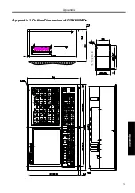
Page 394: ...Appendix 375 Appendix Appendix 1 Outline Dimension of GSK980MDc L N ...

