GSK980MDc Milling CNC System User Manual
408
Appendix
CNC
output
s
adjusted spindle speed output value, in the form of analog voltage, via analog spindle
interface circuit, to spindle frequency converter.
10.3 M Type Gear Shift
This gear shift pattern is valid only in single analog spindle.
To choose M type gear shift, according to data parameter set value and S instruction value, CNC
makes a decision and outputs to PLC that which gear
stage(GR40,GR30,GR2O,GR1O<F034.3,F034.2,F034.1,F034.0>) is needed for the appointed spindle
speed.
After S code outputted , only when CNC issues gear shift instructions to PLC, do CNC output SF
signal.
When there is auto running of any of input instructions S0
~
S9999, CNC outputs spindle motor
rotation instructions, which are corresponding to speed range of the 4 gears pre-set via data parameter, to
spindle motor. At meantime it outputs current gear select signals as well as SF.
The meaning of gear select signal is as follows.
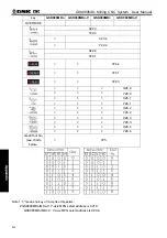
GR10(F34.3) GR10(F34.2) GR20(F34.1) GR10(F34.0) Selective
gear-stage
0 0 0 1 gear-1
0 0 1 0 gear-2
0 1 0 0 gear-3
1 0 0 0 gear-4
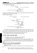
To spindle motor analog spindle output speed instructions like this: as to analog voltage 0
~
10V,
output to analog voltage signal SVC.
M type gear shift has two types to choose, set by bit parameter SGB.
SGB: gear shift types:
0: M type gear shift Type A;
1: M type gear shift Type B
The following are examples of the two gear shift.
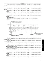
M type gear shift Type A:
As to the data in the image above, descriptions as follows:
Constant VMax:spindle motor Maximum restraint speed (S12-bit code value), that is data parameter
NO.3736
Summary of Contents for 980MDc
Page 19: ...GSK980MDc Milling CNC User Manual XVIII ...
Page 20: ...1 I Programming Programming Ⅰ ...
Page 21: ...GSK980MDc Milling CNC System User Manual 2 I Programming ...
Page 139: ...GSK980MDc Milling CNC System User Manual 120 I Programming ...
Page 191: ...GSK980MDc Milling CNC System User Manual 172 I Programming ...
Page 192: ...173 Ⅱ Operation Ⅱ Operation ...
Page 193: ...GSK980MDc Milling CNC System User Manual 174 Ⅱ Operation ...
Page 200: ...Chapter 1 Operation Mode and Display 181 Ⅱ Operation ...
Page 201: ...GSK980MDc Milling CNC System User Manual 182 Ⅱ Operation ...
Page 249: ...GSK980MDc Milling CNC System User Manual 230 Ⅱ Operation ...
Page 253: ...GSK980MDc Milling CNC System User Manual 234 Ⅱ Operation ...
Page 259: ...GSK980MDc Milling CNC System User Manual 240 Ⅱ Operation ...
Page 265: ...GSK980MDc Milling CNC System User Manual 246 Ⅱ Operation ...
Page 293: ...GSK980MDc Milling CNC System User Manual 274 Ⅱ Operation ...
Page 295: ...GSK980MDc Milling CNC System User Manual 276 Ⅱ Operation ...
Page 319: ...GSK980MDc Milling CNC System User Manual 300 Ⅱ Operation ...
Page 320: ...301 Ⅲ Installation Ⅲ Installation ...
Page 321: ...GSK980MDc Milling CNC System User Manual 302 Ⅲ Installation ...
Page 345: ...GSK980MDc Milling CNC System User Manual 326 Ⅲ Installation ...
Page 391: ...GSK980MDc Milling CNC System User Manual 372 Ⅲ Installation ...
Page 392: ...Appendix 373 Appendix Appendix ...
Page 393: ...GSK980MDc Milling CNC System User Manual 374 Appendix ...
Page 394: ...Appendix 375 Appendix Appendix 1 Outline Dimension of GSK980MDc L N ...


