Chapter
Ⅳ
Tool Nose Radius Compensation
159
Ⅰ
Programming
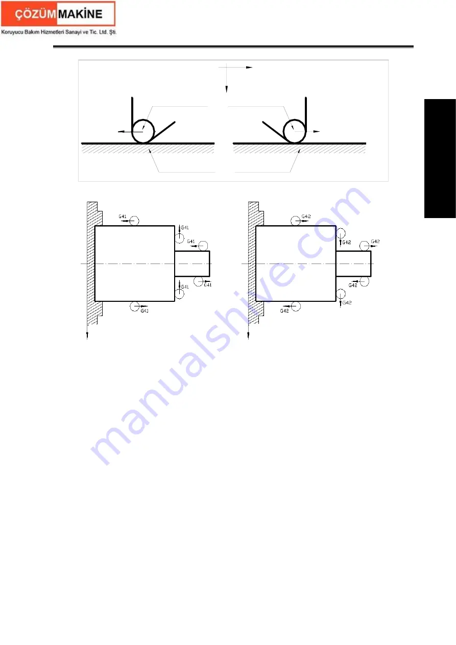
Z
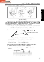
G41:Tool is right to
workpiece from its
movement direction
G42:Tool is left to
workpiece from its
movement direction
Workpiece
Tool
X
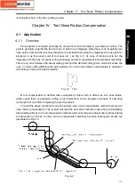
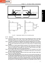
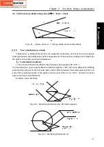
Fig. 4-13 Compensation direction of front coordinate system
4.1.6 Cautions
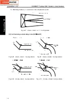
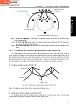
Note 1: In initial state, when the system is in the tool nose radius compensation cancel mode, and the offset
compensation number is not 0 in G41 or G42, the system starts creating the tool nose radius
compensation offset mode; when the offset compensation number is 0, G modal is the G40 state.
Note 2: In creating or cancelling tool compensation, the workpiece machining must not be executed,
otherwise, it causes the overcut or undercut. The system takes the created first movement and the
last movement command before being cancelled as the cutting command in normally machining
workpiece.
Note 3: The tool does not create the offset and starts compensation in the next movement command when
there is no movement command in creating the tool compensation. When there is no movement
command in cancelling tool compensation, the tool does not create the offset and the system
cancels the compensation vector in the next movement command.
Note 4: The next block to create the tool compensation block has the tool compensation cancel modal
command, the system does not execute the tool compensation creation process, but at the moment,
the modal command will change normally.
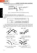
Note 5: The tool nose radius compensation creation and cancel only use G00 or G01 instead of G02 or G03.
When they are specified, No.252 alarms.
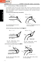
Note 6: In tool nose radius compensation, the tool nose center moves to the end point of the last block and
is vertical with the programmed path of the last when the system executes 3 or more than 3 blocks
without movement command. At the moment, the overcut or undercut creates and the system should
not machine the workpiece in the next block in programming. When 3 or more than 3 blocks without
movement command following the movement command to create the tool nose radius compensation,
the system does not create immediately the tool nose radius compensation but does it after the
X axis
Z axis
Z axis
X axis
Summary of Contents for 988T
Page 6: ...GSK988T Turning CNC System User Manual VI ...
Page 14: ...GSK988T Turning CNC System User Manual XIV ...
Page 15: ...Chapter 1 Programming Fundamentals 1 Ⅰ Programming Ⅰ PROGRAMMING ...
Page 16: ...GSK988T Turning CNC System User Manual 2 Ⅰ Programming ...
Page 194: ...GSK988T Turning CNC System User Manual 180 Ⅰ Programming ...
Page 195: ...Chapter Ⅰ Overview 181 Ⅱ Operation Ⅱ OPERATION ...
Page 196: ...GSK988T Turning CNC System User Manual 182 Ⅱ Operation ...
Page 217: ...Chapter Ⅲ Windows 203 Ⅱ Operation ...
Page 267: ...Chapter Ⅲ Windows 253 Ⅱ Operation Fig 3 51 Fig 3 52 ...

