Chapter
Ⅳ
Tool Nose Radius Compensation
161
Ⅰ
Programming
G01 Z0 F300; (Start cutting)
X16;
Z-14 F200;
G02 X28 W-6 R6;
G01 W-7;
X32;
Z-35;
G40 G00 X90 Z40; (Cancel tool nose radius compensation)
G00 X100 Z50 T0100;
M30;
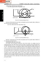
4.2 Tool Nose Radius Compensation Offset Path
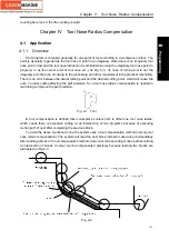
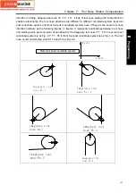
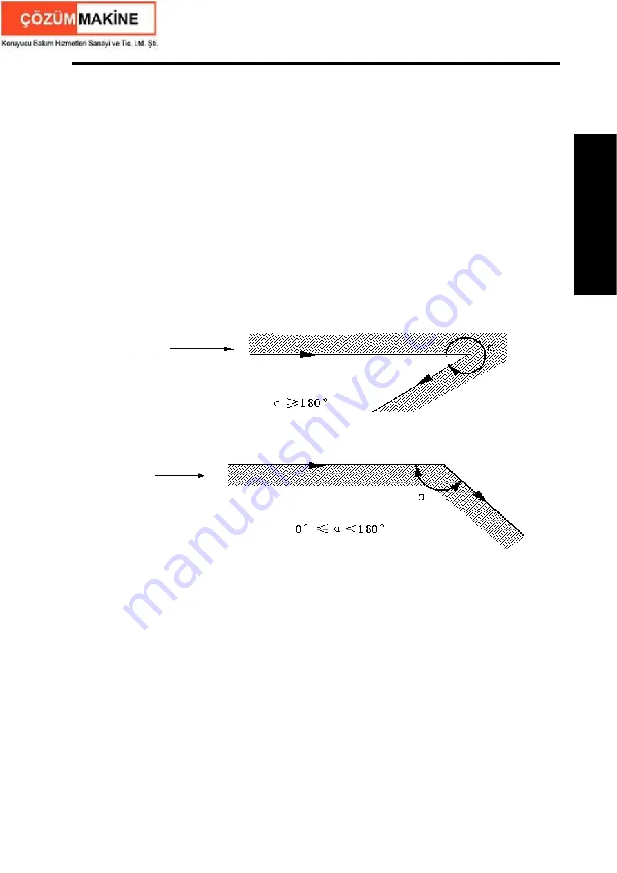
4.2.1 Inner and outer side
Inside
is defined that an angle at intersection of two motion blocks is more than or equal to 180°;
Outside
is 0~180°.
Fig. 4-15
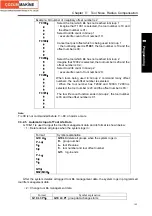
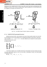
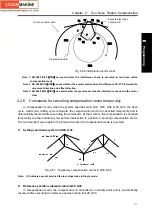
4.2.2 Tool traversing when starting tool
3 steps to execute tool nose radius compensation: tool compensation creation, tool
compensation execution and tool compensation canceling.
Tool traverse is called tool compensation creation (starting tool) from offset canceling to G41 or
G42 execution.
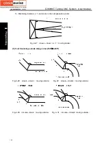
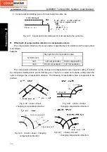
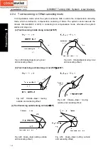
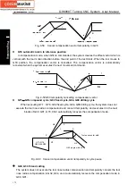
Note: Meanings of S, L, C in the following figures are as follows:
S
――
Stop point of single block; L
――
linear; C
――
circular, R
――
tool radius compensation
;
α――
angle between two blocks.
Workpiece side
Inner
Programmed path
Outer
Programmed path
Workpiece side
Summary of Contents for 988T
Page 6: ...GSK988T Turning CNC System User Manual VI ...
Page 14: ...GSK988T Turning CNC System User Manual XIV ...
Page 15: ...Chapter 1 Programming Fundamentals 1 Ⅰ Programming Ⅰ PROGRAMMING ...
Page 16: ...GSK988T Turning CNC System User Manual 2 Ⅰ Programming ...
Page 194: ...GSK988T Turning CNC System User Manual 180 Ⅰ Programming ...
Page 195: ...Chapter Ⅰ Overview 181 Ⅱ Operation Ⅱ OPERATION ...
Page 196: ...GSK988T Turning CNC System User Manual 182 Ⅱ Operation ...
Page 217: ...Chapter Ⅲ Windows 203 Ⅱ Operation ...
Page 267: ...Chapter Ⅲ Windows 253 Ⅱ Operation Fig 3 51 Fig 3 52 ...

