background image

Chapter 

  Windows 


229

  Operation 

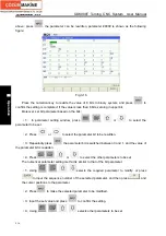
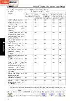
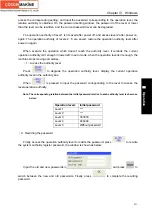
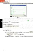
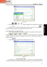
Press 

  to position the cursor to search the parameter position. The search can be done 

in the whole window, and the parameter name and the parameter name must be input correctly.     

Press 

and the window display returns to the previous menu.   


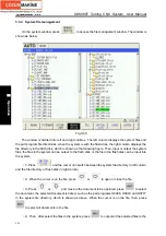
3.4  Setting Window  

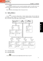
Press 

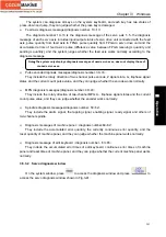
 to access the setting window. It mainly includes windows of the tool offset and 

CNC setting and macro variable, etc. The content can be checked through the corresponding soft 
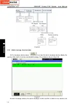
keys. The structure of the soft key layers is shown as below:     


Fig. 3-32 

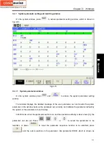
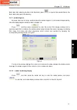
3.4.1  Tool offset setting  

3.4.1.1 Tool offset setting 


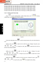
Press 

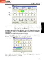
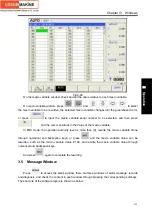
  to access the tool compensation window shown in Fig.3-33:     

Summary of Contents for 988T

Page 1: ...cessary or unallowable operations due to length limitation and products application conditions Therefore the items not presented herein should be regarded as impossible or unallowable Copyright is reserved to GSK CNC Equipment Co Ltd It is illegal for any organization or individual to publish or reprint this manual GSK CNC Equipment Co Ltd reserves the right to ascertain their legal liability ...

Page 2: ...o ensure safe and effective running please read this manual carefully before installation and operation Warning Accident may occur by improper connection and operation This system can only be operated by authorized and qualified personnel Special caution The power supply fixed on in the cabinet is exclusively used for the CNC system made by GSK It can t be applied to other purposes or else it may ...

Page 3: ...ce shortage or damage is found Connection Only qualified personnel can connect the system or check the connection The system must be earthed and the earth resistance must be less than 0 1Ω The earth wire cannot be replaced by zero wire The connection must be correct and firm to avoid any fault or unexpected consequence Connect with surge diode in the specified direction to avoid damage to the syst...

Page 4: ... workpiece be scrapped or the user be injured CAUTION z Functions technical indexes such as precision and speed described in this user manual are only for this system Actual function configuration and technical performance of a machine tool with this CNC system are determined by machine tool builder s design so functions and technical indexes are subject to the user manual from machine tool builde...

Page 5: ... User s Responsibility Be trained with the safety operation of CNC system and familiar with the safety operation procedures Be responsible for the dangers caused by adding changing or altering to the original CNC systems and the accessories Be responsible for the failure to observe the provisions for operation adjustment maintenance installation and storage in the manual This manual is subject to ...

Page 6: ...GSK988T Turning CNC System User Manual VI ...

Page 7: ... between the metric and the inch 14 1 4 5 Linear axis and rotary axis 15 1 5 Structure of an NC Program 15 1 5 1 Program name 16 1 5 2 Block format 16 1 5 3 Word 17 1 5 4 Block number 26 1 5 5 Main program and subprogram 26 1 6 Program Run 27 1 6 1 Sequence of program run 27 1 6 2 Execution sequence of word 28 Chapter II G Commands 29 2 1 Summary 29 2 1 1 G command classification 29 2 1 2 Omitting...

Page 8: ... 16 Threading Cutting 90 2 16 1 Thread Cutting with Constant Lead G32 90 2 16 2 Thread cutting with variable lead G34 93 2 16 3 Thread cutting cycle G92 95 2 16 4 Multiple thread cutting cycle G76 97 2 17 Constant Surface Speed Control G96 Constant Rotational Speed Control G97 103 2 18 Feedrate per Minute G98 Feedrate per Rev G99 105 2 19 Drilling Boring Fixed Cycle Command 106 2 19 1 End drilling...

Page 9: ...mpensation value setting 155 4 1 4 G40 G41 G42 command function 156 4 1 5 Compensation direction 157 4 1 6 Cautions 159 4 1 7 Application 160 4 2 Tool Nose Radius Compensation Offset Path 161 4 2 1 Inner and outer side 161 4 2 2 Tool traversing when starting tool 161 4 2 3 Tool traversing in Offset mode 163 4 2 4 Tool traversing in Offset canceling mode 168 4 2 5 Tool interference check 169 4 2 6 ...

Page 10: ...time 211 3 2 Program Window 212 3 2 1 Local directory and U disk directory 212 3 2 2 MDI program 213 3 2 3 Item times 214 3 3 System Window 214 3 3 1 System parameter setting and rewriting window 215 3 3 2 Screw pitch compensation setting and rewriting window 218 3 3 3 System message and operation authority levels 219 3 3 4 System file management 222 3 3 5 Ladder diagram 223 3 4 Setting Window 229...

Page 11: ...ting a Program 263 Chapter Ⅴ Manual Operation 264 5 1 Manual Reference Position Return 264 5 2 Manual Feed 265 5 3 Increment Feeding 266 5 4 MPG Feeding 267 Chapter Ⅵ Auto Operation 270 6 1 Auto Running 270 6 1 1 Selecting the running program 270 6 1 2 Program running 271 6 1 3 Running from any block 272 6 1 4 Skip 272 6 1 5 G31 skip 273 6 1 6 Stop auto running 273 6 2 MDI Running 274 6 2 1 Editin...

Page 12: ...Output 311 11 3 Parameters Related to Axis Control Setting Unit 311 11 4 Parameters Related to Coordinate System 315 11 5 Parameters Related to the Stroke Detection 317 11 6 Parameters Related to Feedrate 320 11 7 Parameters Related to Control of Acceleration and Deceleration 324 11 8 Parameters Related to Servo and Backlash Compensation 326 11 9 Parameters Related to Input Output 330 11 10 Parame...

Page 13: ... Communication prompt on the operation panel 375 1 9 GSK CAN Communication Prompts 375 1 10 Servo Inner Alarms 377 Appendix 2 Standard Ladder Function Allocation 381 2 1 X Y Addresses Definition 381 2 2 Standard Operation Panel 384 2 2 1 Address X 384 2 2 2 Address Y 386 2 3 Standard PLC Parameter Instruction 389 2 3 1 Parameter K 389 2 3 2 Parameter DT 390 2 3 3 Parameter DC 391 2 3 4 Parameter D...

Page 14: ...GSK988T Turning CNC System User Manual XIV ...

Page 15: ...Chapter 1 Programming Fundamentals 1 Ⅰ Programming Ⅰ PROGRAMMING ...

Page 16: ...GSK988T Turning CNC System User Manual 2 Ⅰ Programming ...

Page 17: ... file transmission and to meet the network teaching and workshop management GSK988T is the best choice for the slant bed CNC turning and turning center Fig 1 1 GSK988T appearance Technical characteristics 5 feed axes including Cs axis 3 axis link 2 analog spindles to realize the turning milling compound machining Command unit 1μm and 0 1μm max speed 60m min max speed 24m min in 0 1μm Optional to G...

Page 18: ...d lenght angle speed can be set Acceleration deceleration function Cutting feed linear exponential Rapid traverse linear Thread cutting linear exponential Initial speed terminal speed and time of acceleration deceleration are set by the parameter Spindle function 2 channel 0V 10V analog voltage output 2 channel spindle encode feedback double spindle control Spindle speed spindle speed specified by...

Page 19: ...compound programming Macro command statement macro command program Program call macro program call with parameters 12 level subprogram nesting Grammar check executing the rapid grammar check for the program do not run the program after it has been edit Communication function RS232 interface part program and parameter transmission DNC machining upgrading PLC program and system software U disc USB U...

Page 20: ...SK988T Turning Machine CNC system which realizes the required electric control requirements of machine tool is convenient to electric design of machine tool and reduces cost of CNC machine tool Softwares used for controlling GSK988T Turning Machine CNC system are divided into system software NC for short and PLC software PLC for short NC system is used for controlling display communication edit de...

Page 21: ...0 X3 76 Z0 G01 Z 1 28 F50 M30 Analyse workpiece drawings and confirm machining processing Edit part programs and record into CNC Test part programs and execute trial run Check part dimension and modify part programs and compensations Execute toolsetting and set tool offsets and coordinates Run part programs and machine workpiece The machining ends and the workpiece is formed ...

Page 22: ...le 1 3 a Axis name Setting value Axis name Setting value X 88 Z 90 Y 89 A 65 B 66 C 67 There is a front tool post and a rear tool post of NC turning machine according to their relative position between the tool post and the spindle Fig 1 5 is a coordinate system of the front tool post and Fig 1 6 is a rear toolpost one It shows exactly the opposite of X axes but the same of Z axes from figures In ...

Page 23: ...01inch diameter 0 0001inch radius 0 001deg 0 0005inch 0 001inch 0 001deg mm input 0 001mm diameter 0 001mm radius 0 001deg 0 00005mm 0 0001mm 0 001deg Inch machine Inch input 0 0001inch diameter 0 0001inch radius 0 001deg 0 00005inch 0 0001inch 0 001deg Table 1 3 c increment system IS C Least input increment Least command increment mm input 0 0001mm diameter 0 0001mm radius 0 0001deg 0 00005mm 0 0...

Page 24: ...dinate system GSK988T Turning CNC System can set 4 reference positions by parameters as follows Y X 2nd reference point 3rd reference point 4th reference point reference point Machine zero Fig 1 6 reference position 1 3 5 Machine coordinate system Machine tool coordinate system is a benchmark one used for CNC counting coordinates and a fixed one on the machine tool Machine tool zero is a fixed poi...

Page 25: ...ink axis when the interpolation is executed The moving distance direction and speed of it are controlled synchronously in the course of running to form the required Composite motion path Positioning control is defined that motion end point of one axis or multiple axes instead of the motion path in the course of running is controlled GSK988T has linear arc and thread interpolation function Linear i...

Page 26: ...the traverse distance programming In the system using the absolute programming or incremental programming is depended on the word of the command as follows Table 1 4 a Absolute value command Incremental value command X movement command X U Y movement command Y V Z movement command Z W C movement command C H A movement command A None B movement command B None The system can select the incremental p...

Page 27: ...diameter programming Table 1 4 b related addresses and data to the diameter or radius programming Word Explanation Diameter programming Radius programming X coordinate polar coordinate Diameter value Radius value X G50 sets X coordinate Diameter value Radius value X increment Diameter value Radius value G71 infeed amount Radius value X finishing allowance in G71 G72 G73 Parameter definition U tool...

Page 28: ...e set to 0 001 Program command The corresponding actual value when DPI is 1 The corresponding actual value when DPI is 0 X1000 without decimal command value 1000mm Unit mm 1 mm Unit least input increment set to 0 001 X1000 0 with decimal command value 1000mm unit mm 1000mm Unit mm The decimal which is less than the least input increment unit is discarded in course of program being executed Example...

Page 29: ...dinate values is the corresponding angle cycle value of per rev set by NO 1260 after the machine moves When NO 1008 Bit 1 RABx is set to 0 the machine rotates according to the shortest distance to the target point For incremental command the machine moves according to the angle defined by the command 1 5 Structure of an NC Program User needs to compile part programs called program according to com...

Page 30: ...m number 0000 9999 the leading zero can be omitted Address O is number of a program name its range is 4 digit integer 0000 9999 the system alarms when the negative program name is input The system ignores NC commands when program are edited and other NC commands are edited in the first line 1 5 2 Block format 1 Format N countless words skip character A block can have or not it generally it is plac...

Page 31: ...or not User can set whether the system automatically creates block number or not in editing program by setting Bit 5 SEQ of NO 0000 2 Use can set the interval value in automatically creating block number by setting NO 3216 Note Sprit explanations 1 When the sprit is used to skip character it is generally placed the beginning of block otherwise and the messages from the sprit to EOB code are ignore...

Page 32: ...mand of axis ISB system 99999 999 99999 999 mm ISB system 9999 9999 9999 9999 inch Z Z absolute coordinate value linear axis 1 ISC system 9999 9999 9999 9999 mm ISC system 999 99999 999 99999 inch Relative command of axis ISB system 99999 999 99999 999 mm ISB system 9999 9999 9999 9999 inch A A absolute coordinate value linear axis 1 ISC system 9999 9999 9999 9999 mm ISC system 999 99999 999 99999...

Page 33: ...9999 9999 mm ISC system 999 99999 999 99999 inch G02 G03 ISB system 99999 999 99999 999 mm ISB system 9999 9999 9999 9999 inch Taper and thread taper 1 in G90 G92 G94 G76 1 ISC system 9999 9999 9999 9999 mm ISC system 999 99999 999 99999 inch G90 G92 G 94 G76 ISB system 0 99999 999 mm ISB system 0 9999 9999 inch Tool retraction 2 in G71 G72 2 ISC system 0 9999 9999 mm ISC system 0 999 99999 inch G...

Page 34: ...nd unit 1 99999999 least command unit G76 Q Initial angle 3 of 1 st circle in thread cutting 3 0 99999999 least command unit default to 0 0 99999999 least command unit default to 0 G32 G34 G 92 Macro program call times assignment 1 9999 default to 1 1 9999 default to 1 G65 G66 L Head quality of multi thread 1 99 default to 1 1 99 default to 1 G92 ISB system 99999 999 99999 999mm ISB system 9999 99...

Page 35: ... GE Greater than or equal to LT Less than LE Less than or equal to Judgement logic is used to brackets following IF WHILE SIN SI Sine ASIN AS Anti sine COS CO Cosine ACOS AC Anti cosine TAN TA Tangent ATAN AT Anti tangent SQRT SQ Square root ABS AB Absolute value ROUN RO Rounding off FIX FI Down integer FUP FU Up integer LN Nature logarithm EXP EX Exponential function OR OR XOR XO OR AND AND AN AN...

Page 36: ...on should have and there must not be the space between the word and the expression For example X 1 110 Z 1 SIN 120 1 When the address values in the above table X Y Z C A B C U V W H I J K R are taken as word address their value ranges are controlled by the following parameters 1 No 0000 2 INI INI input unit 0 metric 1 inch 2 No 1006 0 ROTx ROTx set linear axis or rotary axis 0 linear axis 1 rotary...

Page 37: ...s the least command unit in Table 1 5 3 2 Command value calculation method specified by U W R K is the same that of 1 they meet the value range described in 1 and limit value range according to preparatory function 3 Position specified value commanded by P Q is 0 99999999 data unit is the least command unit in Table 1 5 3 value range is limit by specific preparatory function 2 Word value and state...

Page 38: ... X allowance in finishing Null 0 No Null U Cutting depth in G71 Parameter value Parameter value Yes Parameter value V Y relative coordinate value 0 0 No Current value Z relative coordinate value 0 0 No Current value Z allowance in finishing 空 0 No Null W Cutting depth in G72 Parameter value Parameter value Yes Parameter value 0 0 No Current value G00 H C increment value 0 0 No Current value Polar ...

Page 39: ...tool infeed amount in G74 G75 Null 0 No Null Least cutting amount in G76 roughing Parameter value Parameter value Yes Parameter value 1 st thread cutting depth in G76 thread roughing Null Alarm No Null 1 st circle start angle in thread cutting Null 0 No 0 Q Check offset in spindle fluctuation check Null 0 No the parameter cannot be modified 0 L Macro program call times assignment 1 1 No Null X vec...

Page 40: ... same block number in one program but the block number of target block of program skip has only one otherwise the program skips to the nearest block to the block 4 block number can be placed at will it is suggested that it should be placed by the rising or falling monotonously Note When the block number exceeds the range and the program runs or the grammatical check is done the relevant alarm occu...

Page 41: ...fter the current block runs completely in Edit MDI mode and then a block pointed by the current cursor starts running after the system switches into Auto mode the CYCLE START key is pressed or external cycle start signal is switched on z The program stops run in Manual Jog Handwheel MPG Single Block Program Reference position Return Machine Reference position Return mode and it continuously runs f...

Page 42: ...mitting M signal to PLC when G codes and M98 M99 M9000 M9999 are in the same block When G codes and M S T executed by PLC are in the same block PLC defines M S T and G to be executed simultaneously or execute M S T after G codes Please see User Manual of machine manufacturer for execution sequence of commands Execution sequence of G M except for the above M codes S T defined by GSK988T PLC in the ...

Page 43: ...0 G00 0 G18 are illegal 2 1 1 G command classification G commands are divided into modal G command and non modal G command After a G command is executed its defined function or state remains valid till other G command is specified in the same group this G command is called the modal After the modal G command is executed before its defined function or state is changed the G command cannot be input ...

Page 44: ...nt pitch thread cutting G34 01 Variable pitch thread cutting Modal G40 Tool radius compensation cancel G41 Cutter compensation left G42 07 Cutter compensation right Modal G50 Workpiece setting or max spindle speed setting G52 Local coordinate system setting G53 00 Machine coordinate system setting Non modal G54 Select workpiece coordinate system 1 G55 Select workpiece coordinate system 2 G56 Selec...

Page 45: ... unchanged Note 3 G commands in Group 00 are non modal Note 4 G commands in Group 00 and ones in Group 01 are specified in the same block G commands in Group 00 are valid G commands in Group 01 only change their modal Note 5 Commands in Group 06 09 21 and ones in other groups cannot be in the same block commands in Group 12 and G65 are specified only in a separate block Note 6 When No 3403 Bit6 AD...

Page 46: ...pitch G99 G01 U10 F0 01 G99 feed minute F is input again G00 X80 Z50 M30 Example 2 O0001 G0 X100 Z100 rapidly traverse to X100 Z100 the modal G0 is valid Command address Function Initial value when power on U Cutting depth in G71 51 parameter value U Move distance of X tool retraction in G73 53 parameter value W Cutting depth in G72 51 parameter value W Move distance of X tool retraction in G73 54...

Page 47: ...ute coordinates of end point Zp absolute coordinate of Z end point or one which is parallel to Z W different value of absolute coordinates between starting point and end point C C absolute coordinate of end point H different value of C absolute coordinate between end point and starting point A A absolute coordinate of end point B B absolute coordinate of end point F cutting feedrate IP it is the c...

Page 48: ...G01 IP F__ it can be omitted to G1 Command explanation IP_ it is the end point coordinate value of tool traversing for the absolute command it is the tool traversing distance for the incremental command F_ it is the feedrate of the tool and its ranges is shown below Feed mode Metric mm input Inch inch input ISB system 1 60000 mm min 0 01 2400 inch min G98 ISCsystem 1 24000 mm min 0 01 960 inch min...

Page 49: ...he display value of actual speed does not include the actual speed of rotary axis 2 4 Arc Interpolation G02 G03 Command function The tool traverses along an arc on the specified level Command format 0 2 _ 1 7 _ _ _ 0 3 _ _ G R G X p Y p F G I J 0 2 _ 1 8 _ _ _ 0 3 _ _ G R G X p Z p F G I K 0 2 _ 1 9 _ _ _ 0 3 _ _ G R G Y p Z p F G J K Command explanations Command Description G17 XpYp level selecti...

Page 50: ...e referred to the following table R_ Arc radius with sign it is the radius value when machining range referred to the following table F_ Feedrate along arc its range is the same that of G01 Address Incremental system Metric input mm Inch input inch ISB system 99999 999 99999 999 9999 9999 9999 9999 I J K R ISC system 9999 9999 9999 9999 999 99999 999 99999 I J K have sign symbols according their d...

Page 51: ...s less than or equal to 180 when R is positive Note 7 The alarm occurs when the radius difference between the starting point and the end point of arc exceeds the set value except for 0 of No 3410 When the difference does not exceed the setting value or the set value is 0 the tool firstly executes the arc interpolation along the radius value between the arc and the center and traverse linearly to t...

Page 52: ...y the word P__ X__ or U__ X U value can specify the decimal P value cannot have the decimal otherwise the system alarms Time of P__ X__ or U__ is shown below Address P U X DWT 1 0 001s ISB 0 001s Unit DWT 0 ISC 0 0001s s s Note DWT is the setting value of No 1015 Bit 7 DWT Program O0001 N001 G0 X40 Z5 Rapidly traverse N002 M03 S200 Start the spindle N003 G01 X0 Z0 F900 Approach the workpiece N005 ...

Page 53: ...n G04 Note 6 When G04 and subprogram M98 M99 P__ are in the same block the number following P is the time value of G04 dwell and is also the message of M98 M99 i e subprogram skip message error Note 7 G04 and the interpolation command in Group 1 such as G00 G01 are in the same block G04 is valid G0 G01 only change the modal value of G commands in Group 1 Note 8 When No 3403 Bit 6 AD2 is 0 G04 and ...

Page 54: ...lation the level for cylindrical interpolation must be specified firstly otherwise the alarm occurs the alarm does when G17 G19 is specified to select the level when the cylindrical interpolation is being executed G17 G19 must be specified alone with the rotary axis in the same block otherwise the alarm occurs Note 2 Even if the axis unspecified by the parameter commands the movement value in the ...

Page 55: ...t So when the diameter of the cylindrical is lesser the actual movement amount is not equal to the specified movement amount but the error does not acculmulate MOTION_REV 2π 2 value command 2π 2 MOTION_REV amount motion Actual 2 2 MOTION_REV movement amount per rotation of rotary axis its value is set by No 1260 R Radius of workpiece Round to least input increment Note 7 In the cylindrical interpo...

Page 56: ...N10 G02 Z60 0 C70 0 R10 0 N11 G01 C150 0 N12 G02 Z70 0 C190 0 R75 0 N13 G01 Z110 0 C230 0 N14 G03 Z120 0 C270 0 R75 0 N15 G01 C360 0 N16 G40 Z100 0 N17 G07 1 C0 N18 M15 the spindle is switched into speed control mode N19 M30 The above figure is the side unfolded cylindrical in the program In the figure when the movement amount of rotary aixs C axis specified by the angle is converted into the dist...

Page 57: ...o one linear motion tool motion and one turn motion workpiece turn motion The function is used to end face cutting Command format G12 1 enter the polar coordinate interpolation mode written to G112 G13 1 cancel the polar coordinate interpolation mode written to G113 Command explanation G12 1 G13 1 are specified by an single block After the polar coordinate mode is activated the linear or arc inter...

Page 58: ...66 G67 user macro program command G98 G99 feed rev feed minute The system alarms when other G commands are executed in the polar coordinate interpolation mode Note 6 F feedrate is the tangent speed with the polar coordinate interpolation level rectangular coordinate system in the polar coordinate interpolation mode Note 7 The arc interpolation commanding the arc radius address is determined by the...

Page 59: ...it of MPG movement in incremental feed Note 1 The initial mode of G20 G21 is set by NO 0000 BIT2 INI when the system is turned on Note 2 When G20 G21 switches the current input mode the system must set the beginning of the program and specify in an alone block otherwise the system alarms Note 3 The tool compensation value must input the incremental unit and set it again The tool compensation value...

Page 60: ...the forbidden area there are as follows the system alarms in the next movement block when the forbidden area is in the inner side alarms when the forbidden area is in the outer side Note 9 When the set forbidden area is set by mistaken sequence the system executes the area check of the two points as the top points Note 10 When No 1310 Bit 0 OT2x of the stored travel limit check 2 is set to 1 execu...

Page 61: ... one axis below Fig 2 14 3 The next block of G31 is the absolute coordinate programming of two axes below Program G31 Z200 F100 G01 X100 Z300 Fig 2 15 Skip signal explanation SKIP signal SKIP X3 5 Type input signal Function X3 5 ends the skip cutting I e in a block containing G31 the skip signal becoming the absolute coordinate position of 1 is to be stored in the macro variable 5061 ...

Page 62: ...es to be the tool offset value The function is used to the automatic toolsetting Command format G36 X__ G37 Z__ Explanations X absolute coordinate only used to G36 Z absolute coordinate only used to G37 Non modal G command 00 group Cancel the tool nose radius compensation before using it Only use the absolute programming Define the workpiece coordinate system before using the command Specify the t...

Page 63: ...tool traverses in B zone and the measured point arrival signal of the end point is set to The system alarms when the tool stops at V point Parameter No 6241 No 6242 No 6254 No 6255 are set by the radius value Fig 2 17 Example G50 X760 Z1100 create the workpiece coordinate system T0101 define No 1 tool and execute its tool compensation G36 X200 traverse to X toolsetting point X toolsetting point co...

Page 64: ...cremental value Omit one or all command address for each axis omitting some axis means the axis does not return to the reference position omitting all means the middle point is the tool starting point in the current workpiece coordinate system and the tool does not return to the reference position and keeps stopping Command execution process as Fig 2 18 1 Rapidly position from the current position...

Page 65: ... position return G30 Command function move at the rapidly traverse speed to the middle point specified IP_ and then to the 2nd 3rd and 4th reference position Command format G30 P2 IP__ return to the 2nd reference position G30 P3 IP__ return to the 3rd reference position G30 P4 IP__ return to the 4th reference position Command explanation G30 is non modal IP_ it is the middle point coordinates is s...

Page 66: ...Related Function of Coordinate System The tool position is expressed with the coordinate value of the coordinate system the coordinate value is specified by the programmed axis GSK988T system has three kinds of coordinate system 1 machine coordinate system 2 workpiece coordinate system 3 local coordinate system Fig 2 19 describes the relationship of the three coordinate systems REF M0 EXT G50 G54 ...

Page 67: ...non modal IP_ the absolute coordinate value for each axis in the machine coordinate system must be specified by the absolute value As the following figure the specified axis rapidly moves from A 20 20 in the current workpiece coordinate system to B 8 10 in the machine coordinate system REF Reference position M0 Origin of machine coordinate system is a fixed point on the machine No 1240 value confi...

Page 68: ...odal value in Group 01 2 13 2 Workpiece coordinate system setting G50 The coordinate system used to machining the workpiece is called as the workpiece coordinate system The workpiece coordinate system can be set in advance The set workpiece can change its origin position to set again the position of workpice coordinate system in the machine coordinate system Command format G50 IP__ Command functio...

Page 69: ...te system is set by G50 the absolute coordinate value displayed by G50 is the one that the coordinate value set by G50 adding the tool compensation value which is not executed The difference between the relative coordinates and the machine coordinates is 80 10 when the system executes N4 the difference value is caused because X100Z10 setting G50X20Z20 to create the workpiece coordinate system offs...

Page 70: ...nate systems can change their positions by the external workpiece zero offset value or workpiece zero offset value and their relationship is as Fig 2 22 Fig 2 23 Note 3 Use the following method to change 1 MDI input changes the workpiece coordinate system zero 2 Use G50 to move the workpiece coordinate system Specifying G50 IP_ makes the workpiece coordinate system G54 G59 to set a new workpiece c...

Page 71: ...ate system after the system executes the reference position return it creates the coordinate system uses G55 G59 to switch to other workpiece coordinate system when the system resets No 1201 Bit 7 WZR determines whether the system returns to G54 workpiece coordinate system when No 3402 Bit 6 CLR is set to 1 the modal returns to G54 2 13 4 Local coordinate system setting G52 To be convenient to pro...

Page 72: ...ns to the workpiece coordinate system i e command G52 X0 Z0 Note 1 The local coordinate system setting does not change the workpiece coordinate system and the machine coordinate system Note 2 Commanding G52 can temporarily cancel the offset in the tool nose radius compensation Note 3 In local coordinate system when G50 sets the workpiece coordinate system and the system has not specified the coord...

Page 73: ...vely specifies G17 G19 in the same block and No 3403 Bit 6 AD2 is 0 the last G17 G19 word is valid the system alarms when the parameter is set to 1 Note 6 The multi compound cycle command G70 G76 and the fixed cycle command G90 G92 G94 are used to ZX basic axis level when their functions are specified in other levels the system alarms Note 7 The motion command is not related to the level selection...

Page 74: ...61 G64 belong to Group 15 and their relations with other G groups are referred to Group 5 4 When G01 is executed it is in the exact stop in cutting mode because it is non cutting command 5 When G61 G64 is specified it is value in the next commanded block Fig 2 27 Note The system defaults G64 cutting mode 2 14 Fixed Cycle Command To simplify programming the system defines G command of single machin...

Page 75: ...rate opposite direction to the above mentioned and return to the position which the absolute coordinates and the starting point are the same Z rapidly traverses to return to the starting point and the cycle is completed Fig 2 28 X_ Z_ Coordinates of longitudinal cutting C point in the figure below U_ W_ Movement to end point C point in the figure below of longitudinal cutting F_ Cutting feedrate R...

Page 76: ...gramming Fig 2 29 Cutting path Relative position between cutting end point and starting point with U W R and tool path of U W R with different sign symbols are as Fig 2 28 1 U 0 W 0 R 0 2 U 0 W 0 R 0 3 U 0 W 0 R 0 R U 2 4 U 0 W 0 R 0 R U 2 Fig 2 30 ...

Page 77: ...er surface is completed by radial feeding X and axial Z or X and Z cutting Command format G94 X U __ Z W __ F__ face cutting G94 X U __ Z W __ R__ F__ taper face cutting Command specifications G94 is modal X_ Z_ Coordinate of cutting end point C point in the figure below in the direction of the bottom side U_ W_ Movement to cutting end point C point in the figure below in the direction of bottom s...

Page 78: ...action at the cutting feedrate opposite direction to the above mentioned and returns to the position which the absolute coordinates and the starting point are the same The tool rapidly traverses to return to the starting point and the cycle is completed Fig 2 32 Fig 2 33 Address Incremental system Metric mm input Inch inch input ISB system 99999 999 99999 999mm 9999 9999 9999 9999 inch R ISC syste...

Page 79: ...etween cutting end point and starting point with U W is as Fig 2 32 1 U 0 W 0 R 0 2 U 0 W 0 R 0 3 U 0 W 0 R 0 R W 4 U 0 W 0 R 0 R W Fig 2 34 Example Fig 2 35 rob Φ125 112 Program G00 X130 Z5 M3 S1 G94 X0 Z0 F200 End face cutting X120 Z 110 F300 G00 X120 Z0 cut outer Φ120 ...

Page 80: ...le G72 closed cutting cycle G73 finishing cycle G70 axial grooving multiple cycle G74 axial grooving multiple cycle G75 and multiple thread cutting cycle G76 When the system executes these commands it automatically counts the cutting times and the cutting path according to the programmed path travels of tool infeed and tool retraction executes multiple machining cycle tool infeed cutting retract t...

Page 81: ...g for the finishing path 5 In ns nf blocks there are only G commands G01 G02 G03 G04 G96 G97 G98 G99 G40 G41 G42 and the system cannot call subprograms M98 M99 6 G96 G97 G98 G99 G40 G41 G42 are invalid in G71 and valid in G70 G96 G97 G98 7 When G71 is executed the system can stop the automatic run and manual traverse but return to the position before manual traversing when G71 is executed again ot...

Page 82: ...bols X coordinate offset of roughing path compared to finishing path i e the different value of X absolute coordinates between A and A The system defaults Δu 0 when U Δu is not input i e there is no X finishing allowance for roughing cycle Δw Z finishing allowance range is as the following table diameter with sign symbols X coordinate offset of roughing path compared to finishing path i e the diff...

Page 83: ... traversing tool is still on the middle point of straight line between A and B the tool does not reach or exceed B and after executing the tool infeed Δd e again execute after executing the tool infeed Δd e again the end point of tool traversing reaches B point or exceeds the straight line between A B point and X executes the tool infeed to B point and then the next step is executed Cutting feed f...

Page 84: ...gramming X Z B B C C X Z B B C C A A A A X Z B B C C X Z B B C C A A A A Fig 2 37 Example Fig 2 38 Fig 2 38 Program O0004 G00 X200 Z10 M3 S800 Spindle clockwise with 800 rev min G71 U2 R1 F200 Cutting depth each time 4mm tool retraction in diameter ...

Page 85: ...axis of the level X axis in ZX level is not necessary to monotonous rise or fall and there may be up to 10 groovings which is shown below Fig 2 39 But external contour along Z must mononously rise or fall and the following contour cannot be machined Fig 2 40 The first tool must be vertical the machining can be executed when the shape along Z changes mononously which is shown below Fig 2 41 The too...

Page 86: ...raction amount the tool approaches the workpiece with G1 speed Note 4 For grooving the finishing path ns nf block Z dimension must mononously change always increase or decrease Note 5 For G71 II type when there is arc in finishing path ns nf 3410 parameter the arc radius permits error cannot be non zero i e the permitting function of arc radius error cannot be activated Note 6 Radius error is irre...

Page 87: ...g the roughing path and the blocks are not executed when G72 is executed F S T commands of ns nf blocks are invalid when G72 is executed at the moment F S T commands of G72 blocks are valid F S T of ns nf blocks are valid when executing ns nf to command G70 finishing cycle 3 There are G00 G01 without the word X U in ns block otherwise the system alarms 4 X Z dimensions in finishing path ns nf bloc...

Page 88: ...rved and the system modifies No 5133 value The value of system parameter NO 5133 is regarded as the travel of tool retraction when R e is not input ns Block number of the first block of finishing path nf Block number of the last block of finishing path Δu X finishing allowance in roughing X coordinate offset of roughing path compared to finishing path i e the different value of X absolute coordina...

Page 89: ...oordinate After Z tool infeed Δd e again is executed the end point of traversing tool is still on the middle point of straight line between A and B the tool does not reach or exceed B and after Z executes the tool infeed Δd e again is executed after the tool infeed Δd e is executed again the end point of tool traversing reaches B point or exceeds the straight line between A B point and Z executes ...

Page 90: ...ig 2 46 a Starting point 176 10 80 20 15 20 b c d Z X Program O0005 G00 X176 Z10 M03 S500 Change No 2 tool and execute its compensation spindle rotation with 500 rev min G72 W2 0 R0 5 F300 Tool infeed 2mm tool retraction 2mm G72 P10 Q20 U0 2 W0 1 Roughing a d X roughing allowance 0 2mm and Z 0 1mm N10 G00 Z 55 S800 Rapid traverse Fig 2 46 ...

Page 91: ... roughing the path of each cutting is the offset travel of finishing path the cutting path approaches gradually the finishing one and last cutting path is the finishing one according to the finishing allowance The starting point and end point of G73 are the same one and G73 is applied to roughing for the formed rod G73 is non modal and its path is as Fig 2 40 Command forma G73 U Δi W Δk R d F S T ...

Page 92: ...3 of G73 ns nf block defines the finishing path and the starting point of finishing path start point of ns block is the same these of starting point and end point of G73 called A point the end point of the first block of finishing path ns block is called B point the end point of finishing path end point of nf block is called C point The finishing path is A B C Roughing path It is one group of offs...

Page 93: ...wance as the following table 99 999 99 999 unit mm and is the Z coordinate offset of roughing contour compared to finishing path i e the different value of Z absolute coordinate of A1 compared to A Δw 0 it is the offset of the last roughing path compared to finishing path in Z positive direction The system defaults Δw 0 when W Δw is not input i e there is no Z finishing allowance for roughing cycl...

Page 94: ...d Bd Rapid traverse speed in ns block in G0 cutting feedrate specified by G73 in ns block in G1 Bd Cd Cutting feed Cd A Rapid traverse to starting point Fig 2 47 G73 run path Coordinate offset direction with finishing allowance Δi Δk define the coordinates offset and its direction of roughing Δu Δw define the coordinates offset and cut in direction in finishing Δi Δk Δu Δw can consist of many grou...

Page 95: ...X Z B B C A A A B C C X Z B B C A A A B C C X Z B B C A A A B C C Fig 2 48 Example Fig 2 49 Fig 2 49 Program O0006 G99 G00 X200 Z10 M03 S500 Specify feedrate per rev and position starting point and start spindle G73 U1 0 W1 0 R3 X tool retraction with 2mm Z 1mm ...

Page 96: ...path nf Block number of the last block of finishing path G70 path is defined by programmed one of ns nf blocks Relationships of relative position of ns nf block in G70 G73 blocks are as follows G71 G72 G73 N ns F S Blocks for finishing path N nf G70 P ns Q nf 2 G70 is compiled following ns nf blocks If they are in the front of G71 blocks the system automatically searches and executes ns nf blocks ...

Page 97: ...tinguish them 3 The tool can stop in Auto mode and traverse in Manual mode when G74 is executed but the tool must return to the position before executing in Manual mode when G74 is executed again otherwise the following path will be wrong 4 When the single block is running programs pauses after each axial cutting cycle is completed 5 R Δd must be omitted in blind hole cutting and so there is no di...

Page 98: ...e range is referred to the following table R Δd Travel radius value of radial X tool retraction after cutting to end point of axial cutting The value range is referred to the following table The radial X tool retraction is 0 when R Δd is omitted and the system defaults the axial cutting end point The radial X tool retraction is 0 when P Δi is omitted Address Incremental system metric mm input Inch...

Page 99: ...al X axial rapid tool infeed and its direction is opposite to that of tool retraction When the end point of tool infeed is still on it between A and Af starting point of last axial cutting cycle after the system executes X tool infeed d i radius value i e Dn An 1 and then the system executes start the next axial cutting cycle after the system executes the tool infeed d i the end point reaches Af o...

Page 100: ...ting cycle tool infeeds in axial direction and execute the next radial cutting cycle cut to end point of cutting and then return to starting point starting point and end point are the same one in G75 which is called one radial grooving compound cycle Directions of axial tool infeed and radial tool infeed are defined by relative position between end point X U Z W and starting point of cutting G75 i...

Page 101: ...int of axial tool infeed defining with Cn n 1 2 3 X coordinate of Cn is the same that of cutting end point and the different value of Z coordinate between Cn and An is Δd End point of radial cutting cycle End position of radial tool retraction from the end point of axial tool retraction defined by Dn n 1 2 3 X coordinate of Dn is the same that of starting point Z coordinates of Dn is the same that...

Page 102: ...ates of cutting end point is less than that of starting point in X direction otherwise feed in X positive direction Radial X rapid tool retraction e and its direction is opposite to the feed direction of X executes the cutting feed Δk e again the end point of cutting feed is still in it between starting point An of radial cutting cycle and end point of radial tool infeed Address Incremental system...

Page 103: ...nfeed d k radius value i e Dn An 1 and then execute start the next radial cutting cycle if the end point of tool infeed is not on it between Dn and Af after Z tool infeed d k rapidly traverse to Af and execute to start the first radial cutting cycle Z rapidly moves to point A G75 execution is completed Example Fig 2 53 Fig 2 53 G75 cutting Program O0008 G00 X150 Z50 M3 S500 Start spindle with 500 ...

Page 104: ...g includes continuous thread cutting G32 thread cutting with variable lead G34 Z thread cutting G33 Thread cutting cycle G92 Multiple thread cutting cycle G76 The machine used to thread cutting must be installed with spindle encoder the transmission ratio between spindle and encoder is set by the parameter X or Z traverses to start machine after the system receives spindle signal per rev in thread...

Page 105: ...without the decimal is referred to the following table Q is non modal parameter must be defined every time it is 00 when it is not specified the system specifies Q different value can cut multi thread Q rules 1 Its initial angle is 0 if Q is not specified 2 For continuous thread cutting Q specified by its following thread cutting block except for the first block is invalid namely Q is omitted even...

Page 106: ...cuted Note 3 There is no thread run out when J or J K are omitted K J is the thread run out value when K is omitted Note 4 There is no thread run out when J 0 or J 0 K 0 Note 5 The thread run out value J K when J 0 K 0 Note 6 There is no thread run out when J 0 or K 0 Note 7 If the current block is for thread and the next block is the same the system does not test the spindle encoder signal per re...

Page 107: ...ssion calculated value programs F command For example when the thread with 10 teeth inch is machined using F 25 4 10 programs Note 14 The system automatically checks the spindle speed before machining the thread the system alarms when the spindle speed is not commanded The spindle speed cannot be checked in the course of the machining Example Pitch 2mm δ1 3mm δ2 2mm total cutting depth 2mm with tw...

Page 108: ... occurs when R value exceeds the above range and the pitch exceeds the permissive range because of R increment decrement or the pitch is negative Fig 2 58 Caution It is the same as that of G32 Example First pitch of starting point 4mm increment 0 2mm per rev of spindle Fig 2 59 Variable pitch thread machining Value δ1 4mm δ2 4mm total cutting depth 1mm total cutting cycle 2 times 1st tool infeed 0...

Page 109: ...starting point of cutting When the sign of R is not the same that of U R U 2 F Metric thread pitch is the same that of G32 After F value is executed it is reserved and can be omitted J Travel in the short axis in thread run out is same that of G32 and cannot be less than 0 without direction automatically define its direction according to starting position of program and it is modal parameter If th...

Page 110: ...thread run out is confirmed by No 5130 chamfering value and No 1531 run out angle the run out value of the long axis No 5130 setting value 0 1 F and F is the thread pitch When No 5131 the run out angle is set to 0 the long axis and the short axis execute 45 run out when the setting value is positive integer the run out is done based on the run out value and angle of the long axis the system automa...

Page 111: ...ig 2 62 Program O0012 M3 S300 G0 X150 Z50 T0101 Thread tool G0 X65 Z5 Rapid traverse G92 X58 7 Z 28 F3 J3 K1 Machine thread with 4 times cutting the first tool infeed 1 3mm X57 7 The second tool infeed 1mm X57 The third tool infeed 0 7mm X56 9 The fourth tool infeed 0 1mm M30 2 16 4 Multiple thread cutting cycle G76 Command function Machining thread with specified depth of thread total cutting dep...

Page 112: ...d n is the current roughing cycle times d is the thread cutting depth of first roughing Travel of thread cutting Different value between the current thread current depth and the previous one 1 n n d End point of tool retraction It is the end position of radial X tool retraction after the thread cutting in each thread roughing finishing cycle is completed is defined by E point t replacemen X t repl...

Page 113: ...f system parameter No 5140 is rewritten to minimum cutting travel when Q dmin is not input the system takes No 5140 value as the least cutting value R d It is the cutting travel of thread finishing and is the different value radius value without sign symbols of X absolute coordinates between cut in point Be of thread finishing and Bf of thread roughing After R d is executed the command value d is ...

Page 114: ...9999999 unit 0 0001inch Q dmin ISC system 0 99999999 unit 0 0001mm 0 99999999 unit 0 00001inch ISB system 0 001 99999 999 mm 0 0001 9999 9999 inch R d ISC system 0 0001 9999 9999 mm 0 00001 999 99999 inch ISB system 99999 999 99999 999 mm 9999 9999 9999 9999 inch R i ISC system 9999 9999 9999 9999mm 999 99999 999 99999 inch ISB system 1 99999999 unit 0 001mm 1 99999999 unit 0 0001inch P k ISC syst...

Page 115: ...th C D to the intersection of D E r 0 thread run out X axis rapidly traverses to E point Z axis traverses to A point and the thread roughing cycle is completed to execute the finishing After the tool rapidly traverses to B the cutting depth is k and the cutting travel is d execute the thread finishing at last the tool returns to A point and so the thread finishing cycle is completed If the finishi...

Page 116: ...pth one roughing is executed and its cutting depth is equal to the total cutting depth of roughing Note 8 When the least cutting amount or finishing allowance is more than thread tooth height in the course of thread roughing an alarm occurs Note 9 When the run out length is more than the machining thread length of long axis an alarm occurs Note 10 The system automatically checks the spindle speed ...

Page 117: ...le speed state Max spindle speed limit is valid for G96 and is invalid for G97 S value set by G50 is modal and is value before the new max speed is set Note when G50 S0 is executed the spindle speed is limited in 0 r min the spindle does not rotate in the constant surface control The system does not set the current workpiece coordinate system when G50 sets the constant surface speed control Addres...

Page 118: ... S_ After the system powers on max spindle speed limit value is not defined and its function is invalid Max spindle speed limit value defined by G50 S_ is reserved before it is defined again and its function is valid in G96 Max spindle speed defined by G50 S_ is invalid in G97 but its limit value is reserved Note 1 G96 G97 are modal in the same group and one of them is valid in the same time G97 i...

Page 119: ...se to B point with spindle speed 1910 r min G1 W 30 F200 Cut from B to C with spindle speed 1910 r min X80 W 20 F150 Cut from C to D with spindle speed 1910 r min and surface speed 1194 r min G0 X100 Z100 Rapid retract to A point with spindle speed 955 r min M30 End of program spindle stop and cooling OFF 2 18 Feedrate per Minute G98 Feedrate per Rev G99 Command function Cutting feed rate is speci...

Page 120: ...d that the selected spindle speed should be not lower than min speed of spindle servo or converter Note 3 No 1422 set the upper of the cutting feedrate When the actual cutting feedrate the value is multiplied by the override exceeds the specified upper limit it is clamped to the upper limit value Note 4 No 1403 Bit0 MIF can set the cutting speed unit per minute and the detailed is referred to the ...

Page 121: ...ning axis is the others except for the drilling axis G command Drilling axis Positioning axis G83 G85 Z X and C G87 G89 X Z and C Note C axis can be omitted z Fixed cycle is cancelled G80 or G commands included in Group 01 can cancel the fixed cycle 2 19 1 End drilling cycle G83 side drilling cycle G87 Command format G83 X U _ C H _ Z W _ R_ P_ Q_ F_ K_ M_ or G87 Z W _ C H _ X U _ R_ P_ Q_ F_ K_ M...

Page 122: ...alue is not zero and the parameter RTR NO 5101 2 0 Deep hole drilling cycle Q value is specified Q value is not zero and the parameter RTR NO 5101 2 1 Standard drilling cycle Q value is not specified or Q value is zero G83 G87 are modal remain valid once are specified until the fixed cycle is cancelled z High speed deep hole drilling cycle Q value is specified it is not zero and RTR NO 5101 2 0 Th...

Page 123: ...level where the hole bottom is Pause is executed in the time specified by P Return rapidly to the level where point R is Return rapidly to the initial level Drilling cycle ends Fig 2 69 z Deep hold drilling cycle Q value is specified and RTR NO 5101 2 1 Command format and definition are referred to the previous description High speed deep hole drilling cycle d q q Point R Point R level Initial lev...

Page 124: ...fied Command format G83 X U _ C H _ Z W _ R_ P_ F_ K_ M_ or G87 Z W _ C H _ X U _ R_ P_ F_ K_ M_ Command explanation the command definition is referred to the previous description Execution process The tool rapidly positions to the hole from starting point the hole is determined by the hole position data at the initial level Rapidly position to point R The cutting feed is executed to the hole bott...

Page 125: ...s indexing closes suppose M50 is for closing C axis indexing M30 end of program 2 19 2 End Boring CycleG85 Side Boring Cycle G89 The cycle is used for executing boring operation Command format G85 X U _ C H _ Z W _ R_ P_ F_ K_ M_ or G89 Z W _ C H _ X U _ R_ P_ F_ K_ M_ Command definition X_ C_ or Z_ C_ It is the hole position data and is valid only in the specified block Z W _or X U _ It specifies...

Page 126: ...it when the program is started again Note 2 The single block stops at end point of operation 1 operation 2 or operation 6 Note 3 When drilling boring cycle is executed creating or cancelling tool compensation command is executed the command is valid after the cycle ends 2 20 Tapping Cycle Command GSK988T CNC Turning System uses end tapping cycle G84 and side tapping cycle G88 to complete the tappi...

Page 127: ...g Mode Tapping cycle is divided into common mode and rigid tapping mode and the follow method can specify the rigid tapping mode when N0 5200 0 0 and M29 is not specified the system executes the common tapping mode 1 Specify M29 S before G84 G88 blocks 2 It is specified in the same block in G84 G88 tapping blocks M command for clamping C axis cannot be specified in G84 G88 blocks in the mode 3 G84...

Page 128: ...s the high speed deep hole rigid tapping cycle or deep hole rigid tapping cycle by PCP No 500 5 Q value is not specified or Q value is 0 the standard rigid tapping cycle is selected F_ Cutting feed speed K_ Execution times of program it is used when it is needed M_ M command for clamping C axis it is used when it is needed Tapping feed axis specifies X or Z axis according to G84 G88 G84 specifies ...

Page 129: ...s Command format G84 X U _ C H _ Z W _ R_ Q_ P_ F_ K_ M_ or G88 Z W _ C H _ X U _ R_ Q_ P_ F_ K_ M_ Standard rigid tapping cycle Spindle stop Operation 3 Operation 5 Operation 2 Operation 6 Initial level Hole position Starting point Operation 1 Spindle stop Tool Operation sequence P Pause Z X feed Rapid traverse Spindle rotation Operation 4 Pause at hole bottom Hole bottom level P Spindle rotation...

Page 130: ...me specified by P The spindle rotates reversely and the tapping axis returns to point R level at the specified speed Rapidly return to the initial level Standard rigid tapping cycle ends Fig 2 74 z Deep hole rigid tapping cycle Q value is specified it is not zero and RTR NO 5200 5 1 The cycle executes the deep hole rigid tapping operation Command format G84 X U _ C H _ Z W _ R_ Q_ P_ F_ K_ M_ or G...

Page 131: ...guish F98 G99 for the spindle the feedrate is the specified spindle speed and extraction override The extraction override is fixed to 100 when the parameter DOV No 5200 4 whether the tool retraction is valid in the rigid tapping is set to 0 When DOV No 5200 4 is set to 1 it is divided into the following conditions 1 The extraction override is set by No 5211 it is the override value in rigid tappin...

Page 132: ...ue No 5213 which does not exceed the cutting amount q when the deep hole tapping cycle is executed Note 4 R is the distance from the initial level to point R and is specified by radius value and the initial level is considered to R level after it is omitted Note 5 G84 88 is used for dry run Feedrate F is the one in Dry run mode Note 6 For feed pause single block when G84 G88 fixed cycle is at the ...

Page 133: ...read tapping Before G84 G88 is executed the CNC checks the selection signal s state of rigid tapping spindle rotation to confirm the rotation of tapping axis When RGROD signal is set to 1 and G84 G88 executes the infeed the spindle rotates forward when the tool retracts the spindle rotates reversely which is the normal thread tapping when RGROD signal is set to 1 and the infeed is done the spindle...

Page 134: ... R_ P_ F_ K_ M_ or G88 Z W _ C H _ X U _ R_ P_ F_ K_ M_ Command explanation X_ C_ or Z_ C_ It is the hole position data and is valid only in the specified block the hole position data can specify other valid axes except for X Z C Z W _ or X U _ It specifies the coordinate value of hole bottom by using absolute coordinate or specifies the distance from R level to the hole bottom by using incrementa...

Page 135: ...specified before G84 G88 is commanded and the CNC confirms the M command of spindle CCW according to the previous spindle rotation direction of G84 G88 when the direction is not specified the spindle rotation M03 CW is defaulted in G84 G88 common tapping cycle Execution process The tool rapidly positions to the hole from starting point the hole is determined by the hole position data at the initia...

Page 136: ...8 without cutting the workpiece it is not dry run The operator actually observes the coordinate difference between the position where the spindle stops at the hole bottom and G84 G88 starting point and then modifies the program to reserve the enough hole depth before G84 G88 is executed Note 2 Before the tapping cycle is executed the spindle s rotation direction i e command the spindle rotation CW...

Page 137: ... per minute G0 X0 Z200 X and Z position to the starting point M3 S800 the spindle rotates CW at the speed 800 r min the spindle starts rotation after the block is executed G84 Z160 P1000 F1600 starting point is X0 Z200 which is same as the hole position hole bottom position is X0 Z160 and the pause time is 1s the thread lead is 2 according to F and S value G84 is the common tapping cycle when it i...

Page 138: ...erical value following C specifies the distance from chamfering starting point to end point of the imaginary cornering intersection which is defined to the imaginary existing cornering when the chamfering is not executed Fig 2 79 Corning R The numerical value following R specifies corning R radius Fig 2 80 Incremental system Metric input mm Inch input inch ISB system 99999 999 99999 999 mm 99999 9...

Page 139: ...er chamfering or corning R Note 5 When two linear interpolation operations are executed and their angle difference is within 1 the movement of chamfering coring R block is 0 When linear interpolation and circular interpolation operations are executed and angle difference of their tangent at the intersection point is within 1 the movement of corning R block is 0 When two circular interpolation oper...

Page 140: ... the address value Example F 203 203 15 it is the same those of F15 functions Z 210 210 250 it is the same those of Z 250 functions G 230 230 3 it is the same those of G3 functions When the variable value is used in program the decimal point can be omitted Example 1 123 the actual value of 1 is 123 000 When the variable value followed the axis command address has the decimal point the data less th...

Page 141: ...e defined by the address it cannot be used for example 230 120 M 230 exceeds the max command value Note 3 The system cannot identify 0 and 0 4 0 X 4 is taken as X 0 Note 4 When the variable is used to the address data the other except for the valid digit is rounded Note 5 The number followed by the address can use Formular to replace The system takes Word address Formular or word address Formular ...

Page 142: ...nsation value The system variable of the tool compensation storage area is 1501 2999 The variable numbers divided exactly in the above range are illegal The variable number of 2201 2299 2901 2999 alarm The concrete range are referred to the following table Set the axis number to be n 1 5 the compensation number to be m 1 99 the offset variable number of the axis to be 1600 n 1 100 m the wear varia...

Page 143: ...system displays only one prompt The variable is only be written instead of being read Variable Function 3006 When the system executes the assignment statement of 3000 1 it stops the run and displays only one prompt message The alarm message only displays 26 characters 13 Chinese characters and the system only displays the first 26 characters when there are more than it The value of the alarm numbe...

Page 144: ...4014 G54 G55 G56 G57 G58 G59 No 14group 4015 No 15group 4016 G17 G18 G19 No 16group 4022 No 22group 4109 F command 4113 M command 4119 S command 4120 T command Example When the system executes 1 4016 1 value is 17 18 or 19 The system alarms when the reading writing modal value is G command which cannot be used by the system 7 Current position The position message is only read instead of being writ...

Page 145: ...able is the state value of the system and is buffered in advance when multi cycles are executed so the attained system variable is the value before the multi cycle command instead of the current value to avoid using the system variable in the cycle body of the multi cycles 2 22 3 Operation and jump command 1 Operation command Variables can execute all kinds of operations and their operation comman...

Page 146: ...least increment FUP i FUP j Floating UP integer In puls quantity i is more than or equal to j in the negative i is less than or equal to j FIX i FIX j Floating FIX integer In puls quantity i is less than or equal to j in the negative i is more than or equal to j Natural logarithm i LN j Execute natural logarithm The system alarms when j is zero or less than zero Exponential function i EXP j Execut...

Page 147: ...is specified 1 225 When NO 6004 No 0 digit NAT is set to 1 180 180 Example when 1 ATAN 1 1 is specified 1 135 j K can be the constant In division or TAN 90 the division is specified to 0 P S alarms 9 The function ROUND is used to NC command or macro statement which rounds the data with the decimal point It is used to NC statement which rounds according to the least setting unit when it is used to ...

Page 148: ...change the control flow and there are three kind of transfer and repetition operation the unconditional transfer GOTO the conditional transfer IF GOTO IF THEN and WHILE DO repetition Command format GOTO n Command function Skip to the line number n without condition Command format IF Logical expression THEN expression Command function When the logical expression is valid the system executes one fol...

Page 149: ...repetition between DO and END Note 6 In using EQ NE logical operation expression Null and zero have the different result Null is taken as the zero in conditional expression Note 7 The macro program statement cannot be used with NC statement together and the macro program statement definition is as follows Block including arithmetic or logical operation Block including the control statement such as...

Page 150: ...and transfers the argument to the called macro program Command explanations P specify the macro program to be called L times of calling the macro program and its default is 1 and its range is 1 9999 Argument list data transferred to macro programs Argument specification Two types of argument specification are available Argument specification I uses letters other than G L O N and P once each Argume...

Page 151: ...cified later takes precedence Note 5 Calls can be nested to a depth of four levels including simple calls G65 and modal calls G66 This does not include subprogram call M98 Note 6 Whether the units used for argument without a decimal point correspond to the least input increment of each address is related to the parameter DPI No 3401 0 Note 7 G65 G66 cannot be in the same block with NC code otherwi...

Page 152: ...nt and the use methods of P L the argument are the same those of G65 Note 3 Can t call macro program in the block without movement commands but with the auxiliary function Note 4 The local variable argument is specified only in G66 block and the system does not set it again when each modal call is executed Note 5 Cannot specify the macro call command in MDI mode Note 6 When the reset is executed b...

Page 153: ...e program is executed again Except for the above mentioned function executed by NC M02 function is also defined by PLC ladder diagram as follows current output of CNC is reserved after M02 is executed 3 1 2 End of program run M30 Command format M30 Command function In Auto mode after other commands of current block are executed in M30 the automatic run stops the amount of workpiece is added 1 the ...

Page 154: ...When the subprogram is called one time can be omitted in inputting the number behind P at the same time the leading zero of the called subprogram number can be omitted and the system does not alarms Example M98 P12 it expresses to call the subprogram O0012 one time the leading zero cannot be omitted when the subprogram call times are more than one The called subprogram name in M98 must be the prog...

Page 155: ...en P98P__ call itself Note 4 The system alarms when M98 is commanded and the subprogram is called without P command 3 1 6 Subprogram Call M198 Command format M198 P Command function in Auto mode when M198 is executed and the other commands in the current block has been performed the CNC calls the subprogram in the external input output device usually it is U disk specified by P 3 1 7 Return from S...

Page 156: ...am Note 4 In Auto mode the system ignores the line and returns to the beginning of the file to perform the execution when the main program ends in M99 and specifies the line number following P 3 1 8 The Following M commands for standard ladder some functions modified by K parameters M3 spindle rotation CW M4 spindle rotation CCW M5 spindle stop M8 cooling ON M9 spindle OFF M10 tailstock forward M1...

Page 157: ...at S Command function the spindle speed is defined and the system outputs 0 10V analog voltage to control spindle servo or converter to realize the stepless timing S command value is not reserved and it is 0 after the system is switched on Command explanation spindle speed analog voltage control command means the set spindle speed its value range is referred to Table 1 4 and the leading zero can b...

Page 158: ... in 50 120 and it is not reserved when the spindle override is switched off Refer to the operations of spindle override in OPERATION Ⅱ 3 3 Tool Function 3 3 1 Tool offset T functions of GSK988T automatic tool change and executing tool offset Control logic of automatic tool change is executed by PLC and tool offset is executed by NC Command format T Command function The automatic tool post rotates ...

Page 159: ... 0 and X tool length compensation value is 10mm No 5004 Bit1 is set to 1 and X tool length compensation value is 10mm the diameter of workpiece external diameter is 20mm Fig 3 6 is to create execute and cancel the tool offset in movement mode Fig 3 6 Creation execution and cancellation of tool length G01 X100 Z100 T0101 Block 1 start to execute the tool offset G01 W150 Block 2 tool offset G01 X50 ...

Page 160: ...pensation Change 2 tool and execute its offset by the tool traversing with 12mm in X positive direction and 23mm in Z negative direction State of T T0303 Coordinates displaying Incremental coordinates U 24 560 W 13 452 Absolute coordinates X 0 000 Z 0 000 Change 3 tool and execute its offset by the tool traversing with 12 56mm in X positive direction and 36 452mm in Z positive direction State of T...

Page 161: ...Note 6 After executing the miscellaneous function lock is valid the system does not execute the tool change when T command is executed but the tool offset is executed When using the miscellaneous function lock checks the program function it is executed in the safety position 3 3 2 Tool Life Management When the tool life management is used TLF No 8132 0 is set to 1 The tools are divided into many g...

Page 162: ...65535 times Note Even if the same tool group number is specified many time in one program the used times cannot be accumulated and the new tool is not also selected 3 3 2 3 Tool Life Counting and Activating M Command When the life counting is specified by times the life reaches when the tool life counting is specified and M command is activated The tool change signal does not output even if there ...

Page 163: ...command many offset numbers the next offset number is selected When the tool number has T2002 and T2003 T2003 is selected the tool number is 20 and the offset number is 03 The tool life count function ends in Group 2 the tool number is 03 and the offset number is 01 Note T 99 is not commanded before T 88 an alarm occurs 3 3 2 5 Automatic Input of Tool Life Data G10 G11 is used to input the tool li...

Page 164: ...rameter LTM No 6800 2 3 3 2 6 Processing after tool life ending The tool change signal is output when the tool life counting is done and the last tool life has reached in the group When the life counting is specified by time and the last tool life has reached in the group the tool change signal is output immediately When the number of times is specified the last tool life has reached in the group ...

Page 165: ...r between the actual cutting point and the desired cutting point which will cause the over or under cutting affecting the part precision So a tool nose radius compensation is needed in machining to improve the part precision Fig 4 1 Tool B tool compensation is defined that a workpiece contour path is offset one tool nose radius which cause there is excessive cutting at an intersection of two progr...

Page 166: ...nose circular radius compensation In actual machining suppose that there are different position relationship between tool nose point and tool nose circular center point and so it must create correct its direction of imaginary tool nose From tool nose center to imaginary tool nose set imaginary tool nose numbers according to tool Tool nose path is the same as programming Finishing when using tool n...

Page 167: ...ose direction numbers as the following figures In figures it represents relationships between tool nose and starting point and end point of arrowhead is the imaginary tool nose T1 T8 in rear tool post coordinate system is as Fig 4 7 T1 T8 in front tool post coordinate system is as Fig 4 8 The tool nose center and starting point for T0 and T9 as Fig 4 9 Z axis X axis Imaginary tool nose No 1 Imagin...

Page 168: ...nary tool nose No 8 Fig 4 7 Imaginary tool nose number in rear tool post coordinate system Z axis X axis Imaginary tool nose No 1 Imaginary tool nose No 2 Imaginary tool nose No 3 Imaginary tool nose No 4 Imaginary tool nose No 5 Imaginary tool nose No 6 Front tool post coordinate system ...

Page 169: ...4 1 R is tool nose radius compensation value T is imaginary tool nose number and the radius compensation value is the sum of offset radius and wear radius Table 4 1 Display window of system tool nose radius compensation value Tool offset No X Z R T Offset 0 000 0 000 0 380 001 Wear 0 000 0 000 0 000 3 Offset 10 000 10 000 0 250 002 Wear 0 020 0 040 0 000 3 Offset 14 000 15 000 1 200 003 Wear 1 020...

Page 170: ...and function Taking the previous and the current position increment as the programmed path can cancel the tool compensation mode and its direction is the compensation direction of the previous When the system specifies I J I K or J K the vector defined by it can replace the current position increment to execute the count Command format X Z T In machining workpiece the tool offset cannot easily com...

Page 171: ...pecified by G41 in front tool post coordinate system G42 Tool nose radius right compensation is specified by G42 in rear tool post coordinate system and tool nose radius left compensation is specified by G42 in front tool post coordinate system Xp X and its parallel axis Yp Y and its parallel axis Zp Z and its parallel axis I X and the cancel vector radius value of its parallel axis J Y and the ca...

Page 172: ... 158 Ⅰ Programming Z X G42 Tool is right to workpiece from its movement direction G41 Tool is left to workpiece from its movement direction Workpiece Tool Fig 4 12 Compensation direction of rear coordinate system Z axis Z axis X axis X axis ...

Page 173: ...eating the tool compensation When there is no movement command in cancelling tool compensation the tool does not create the offset and the system cancels the compensation vector in the next movement command Note 4 The next block to create the tool compensation block has the tool compensation cancel modal command the system does not execute the tool compensation creation process but at the moment t...

Page 174: ...ol nose radius compensation mode the system must not be switched to other levels otherwise No 253 alarms Note 10 In tool nose radius compensation mode the system cancels the tool compensation mode in RESET M30 or M02 mode Note 11 In MDI mode the system cannot execute the tool nose radius compensation creation and its cancel When the system specifies the tool nose radius compensation command it exe...

Page 175: ...equal to 180 Outside is 0 180 Fig 4 15 4 2 2 Tool traversing when starting tool 3 steps to execute tool nose radius compensation tool compensation creation tool compensation execution and tool compensation canceling Tool traverse is called tool compensation creation starting tool from offset canceling to G41 or G42 execution Note Meanings of S L C in the following figures are as follows S Stop poi...

Page 176: ...g tool inside Fig 4 17 Linear circular starting tool inside b Tool traversing inside along corner 180 α 90 Fig 4 18 Linear linear starting tool outside Fig 4 19 Linear circular starting tool outside c Tool traversing inside along corner α 90 Fig 4 20 Linear linear starting tool outside Fig 4 21 Linear circular starting tool outside ...

Page 177: ...ling it z Offset path without changing compensation direction in compensation mode a Tool traversing inside along corner α 180 Fig 4 23 linear linear moving inside Fig 4 24 linear circular moving inside Fig 4 25 Circular linear moving inside Fig 4 26 Circular circular moving inside d Tool traversing inside along corner α 1 linear linear Fig 4 22 Linear linear α 1 starting tool outside ...

Page 178: ...and zoom in the compensation vector Fig 4 27 Linear linear α 1 moving inside b Tool traversing outside along corner 180 α 90 Fig 4 28 Linear linear moving outside Fig 29 Linear circular moving outside Fig 4 30 circular linear moving outside Fig 4 31 circular circular moving outside ...

Page 179: ...outside along corner α 90 Fig 4 32 Linear Linea moving outside Fig 4 33 Linear circular moving outside Fig 4 34 Circular linear moving outside Fig 4 35 Circular circular moving outside d Special cutting 1 Without intersection r r Fig 4 36 Paths without intersection after offset ...

Page 180: ...on Right compensation G42 Right compensation Left compensation The compensation direction can be changed in compensation mode in special cutting it cannot be changed at starting block and its following one There is no inside and outside cutting when the system changes the compensation direction The following compensation value is supposed to be positive Fig 4 38 Linear linear changing compensation...

Page 181: ...vector perpendicular to block B is created from its starting point i Linear Linear Fig 4 42 Linear linear no intersection changing compensation direction ii Linear circular Fig 4 43 Linear circular without intersection changing compensation direction iii Circular circular Fig 4 44 Circular circular without intersection changing compensation direction ...

Page 182: ...de otherwise the system alarms and stops run a Tool traversing inside along corner α 180 b Tool traversing outside along corner 180 α 90 c Tool traversing outside along corner α 90 Fig 4 50 Linear linear cutting outside and canceling offset Fig 4 49 Linear linear cutting outside and canceling offset Fig 4 46 Circular linear moving inner and canceling offset Fig 4 45 Circular linear moving inner an...

Page 183: ...ated but the system cannot find out all tool interferences 1 Fundamental conditions 1 The tool path direction is different that of program path angle is 90 270 2 In machining arc there is great difference the two angles α 180 the one is between the starting point and the end point of the tool center path and the other is between the starting point and the end point of the programmed path or the sy...

Page 184: ...ates the vector V1 V2 V3 and V4 and the section between N20 and N30 creates V5 V6 V7 V8 The system executes the interference check to the last vectors in the above two group of vector i e V4 and V5 V4 and V5 are ignored when there is the interference the system checks V3 and V6 and they are ignored when there is the interference the system does V2 and V7 and they are ignored when there is the inte...

Page 185: ... cancelled temporarily and is automatically resumed after executing the commands At the moment the compensation is cancelled temporarily and the tool directly moves from intersection to a point for canceling compensation vector The tool directly moves again to the intersection after the compensation mode is resumed z Setting coordinate system in G50 G52 Fig 4 57 Temporary compensation vector in G5...

Page 186: ...porarily cancelling compensation vector z G71 G76 compound cycle G92 fixed cycle G84 G88 drilling cycle When executing G71 G76 G92 fixed cycle G84 G88 drilling cycle the system does not execute the tool nose radius compensation and cancel it temporarily and executes it in the next blocks of G00 G01 G70 CNC automatically recovers the compensation mode Tool nose center path N5 S N6 r S L r N8 N7 G50...

Page 187: ...having creating C tool compensation state the system firstly cancels C tool compensation state in G90 G94 and executes the infeed tool to the intersection point of the tool nose center based on the tool nose center parallel programmed path and at last to the positioning point The system creates C tool compensation again in the next G00 G01 D After the system cancels the tool radius compensation th...

Page 188: ... roughing In G70 the compensation mode is not cancelled after the cycle end the system continuously executes the compensation in the fixed point which causes the undercut of the finishing cycle in the last block so the last should exceeds one tool radius value of the workpiece in programming Fig 4 65 G70 radius compensation mode 4 2 7 Particulars z Inside chamfer machining less than tool nose radi...

Page 189: ... and the system alarms No 257 when starting the previous block or chamfer moving Tool nose center path Display alarm and stop working Overcutting Programmed path Fig 4 67 machining a grooving less than tool nose radius z Machining a inner sidestep less than 90 When the system machines a inner sidestep less than or equal to 90 and the machining path length is less than the tool nose radius there wi...

Page 190: ... corner motion and the second vector will be ignored When the two axis increments of the movement vector in the compensation level are less than the setting values of No 5010 CLV the second vector is ignored but it is not ignored when the interpolation block is the arc Fig 4 69 corner motion z Changing compensation value a The system executes the tool change in the compensation cancel mode the com...

Page 191: ... again the circle center position specified by IJK and confirms the circle center position according to the radius counted by IJK to execute the radius compensation When the counted radius is too small not to reach the end point of the arc No 254 alarm creates Note At the moment there is a difference between the counted arc and the specified in programming and the function is sued to regulate the ...

Page 192: ...e vertical before the last movement command when there is a optional symbol in tool radius compensation So please do not use the optional block function in the tool radius compensation to avoid the overcut When No 6000 Bit5 SBM is set to 1 the macro statement can stop in single block and is taken as the non movement block in the tool nose radius compensation at the moment which causes the abnormal...

Page 193: ... to 0 When the system runs in AUTO mode in absolute command programming and the single block run stops to insert MDI mode and then starts AUTO mode at the moment transfers the vector of starting point of the next block and forms other vectors based on the next two blocks the offset can be executed from PC and the tool path is as follows Fig 4 74 insert tool offset of block in MDI mode When PA PB P...

Page 194: ...GSK988T Turning CNC System User Manual 180 Ⅰ Programming ...

Page 195: ...Chapter Ⅰ Overview 181 Ⅱ Operation Ⅱ OPERATION ...

Page 196: ...GSK988T Turning CNC System User Manual 182 Ⅱ Operation ...

Page 197: ...rding to the program command This operation is called the automatic run See Chapter 6 1 program Fig 1 1 Automatic run z MDI run After a program is input in MDI window the machine runs according to the program command and this operation is called MDI mode run See Chapter 6 2 z Reference position return CNC machine has a special point which is used to determine the position of the worktable of the m...

Page 198: ...tch the button or the MPG on the machine operation panel Fig 1 3 1 Manual manual continuous feed see 5 2 When the press key is kept down the tool continuously traverses 2 Incremental feed see 5 3 The tool only traverses some distance when the key is pressed once z DNC run The system directly reads the programs to run the machine by the external input output device instead of that the program is sa...

Page 199: ...o any tools can machine the workpiece shape specified by the programs The Value related to the tool dimension is called the offset See Chapter Ⅷ z CNC setting CNC setting includes system setting coordinate setting system time setting system IP setting See Chapter 3 4 z Macro variable setting The system can support all kinds of macro program edit the variable required by the macro program is set he...

Page 200: ...ter 3 1 Position Display Window Fig 1 6 Displaying alarm When the failure occurs in the course of run the corresponding mistaken commands and the alarm message are displayed in the window shown in Fig 1 7 The detailed explanations related to the alarm message are referred to Appendix Ⅰ Fig 1 7 Displaying machined workpiece count and operation time Display the machined workpiece count run time and ...

Page 201: ...Chapter Ⅰ Overview 187 Ⅱ Operation Fig 1 8 1 4 System 1 4 1 System panel GSK988T system panel adopts 8 4 LCD and its appearance is shown in Fig 1 9 ...

Page 202: ... System key definitions Keys Name Introduction of the function Reset key CNC reset feeding and output stop etc Keys of address numerical and symbol Input the address number and symbol press shift key and take the above address or symbol Otherwise take the address below ...

Page 203: ...ine during editing the program Change key Switch between the message and the display with function of Tab key and forming the shortcut keys with the other keys during editing the program Backspace key Delete the program and the character etc ahead Cancel key Cancel the operation Delete key Cancel the program and the character etc backward Cursor keys Control the cursors to move up down left and ri...

Page 204: ...oft key can display the content of some sub page in the current window or some operations in the current window are executed The soft keys of GSK988T have 10 in the below of the screen shown below Soft key function Switch the sub pages in the current window Operate on the current secondary window such as editing and rewriting the Value or displaying the content etc 1 5 Machine Operation Panel 1 5 ...

Page 205: ... GSK988T machine panel is defined by PLC program ladder diagram and about the detailed function of each key refer to the manual of the machine manufacturer The machine panel is taken as the reference Function of the machine panel each key defined by GSK988T standard PLC program refer to the following list State indication The indicator for each axis reference position return Running indicator Alar...

Page 206: ...alue control mode is valid Auto mode MDI mode edit mode reference position return mode MPG mode single step mode manual mode and DNC mode Feedrate override knob Adjust the feedrate Auto mode MDI mode Edit mode Reference position return mode MPG mode Step mode DNC mode Manual tool change keys Manual tool change Reference position return mode MPG mode single step mode and manual mode Position record...

Page 207: ...trol axes option keys Each axis option in MPG mode MPG mode Option keys of MPG single step increment and rapid override MPG movement value of each grid 0 001 0 01 0 1 1 mm Single step movement value of each step 0 001 0 01 0 1 1 mm Rapid override F0 F25 50 and F100 Auto mode MDI mode reference position return mode MPG mode single step mode manual mode and DNC mode Single block switch Switch betwee...

Page 208: ...s valid its indicator is on when there is M01 in the block move to the block and the running stops Auto mode MDI mode and DNC mode Edit key Access edit mode Edit mode Auto key Access the auto mode Auto mode MDI key Access MDI mode MDI mode Reference position return key Access reference position return mode Reference position return mode Single step MPG key Access single step or MPG mode One mode i...

Page 209: ...DNC mode Power on off keys System power of off switch Auto mode MDI mode edit mode reference position return mode MPG mode single step mode manual mode and DNC mode Overtravel release key Cancel machine limit MPG mode and manual mode Program protection switch The protection program can t be changed at random Auto mode MDI mode edit mode reference position return mode MPG mode single step mode manu...

Page 210: ...d 1 The machine is normal 2 The power supply and the voltage comply with the requirements 3 The connection is right and fixed After GSK988T powers on the window is shown as below Fig 2 1 Then GSK988T self detects and initializes After the system completes the self detection and the initialization the window of the present position absolute coordinate displays Fig 2 2 ...

Page 211: ...t switch is on the system decelerates till stopping and it alarms overtravel During auto running when the machine moves along one axis and touches the limit switch the tool decelerates and stops as long as it traverses along all axes and the system alarms overtravel During the manual operation only the axis which the tool touches its limit switch decelerates and stops while the tool still traverse...

Page 212: ...n return through G28 each limit becomes valid After connecting the power supply if the reference position is in the limited area it alarms immediately Display the alarm time It alarms immediately before or after the tool enters the forbidden area which is set by the 7th bit of 1300 of parameter BFA Overtravel alarm release When the tool can t traverse in the forbidden area switch into the manual m...

Page 213: ...s valid and then CNC works in the emergency situation and the machine stops moving at once all output is off such as the revolving of the spindle and the cooling fluid After releasing the emergency stop button the alarm is released CNC resets Note 1 Before releasing the emergency stop alarm confirm the trouble is shot Note 2 Before power on and off press the emergence stop button to reduce the ele...

Page 214: ...ive to one main window and each main window also includes many windows and the soft keys Note Press RELATIVE COORDINATE SETTING key in all position windows and the system automatically skips the relative coordinate window to execute the relative coordinate setting Note 1 soft key 2 LOCAL switch the windows by the function key POSITION 3 soft key in blue font 4 continuous menu key the first right s...

Page 215: ...Chapter Ⅲ Windows 201 Ⅱ Operation Note It can be displayed after U disk is inserted in the U disk catalog ...

Page 216: ... 202 Ⅱ Operation Note 1 The servo parameter is displayed only when the system servo communication function is valid and all servo axes are connected Note 2 The operations about the file management are valid only when the U disk is inserted ...

Page 217: ...Chapter Ⅲ Windows 203 Ⅱ Operation ...

Page 218: ...GSK988T Turning CNC System User Manual 204 Ⅱ Operation Note The servo diagnosis is displayed only when the system servo communication function is valid and all servo axes are connected ...

Page 219: ... The displayed content is different according to the different allocation and the diagram form and all content of the related window are based on the standard 2 axis turning machine allocation Press and the system enters the window and the position window includes the absolute coordinate the relative coordinate the machine coordinate and other sub page shown in Fig 3 2 the corresponding soft key c...

Page 220: ... position of the tool in the current workpiece coordinate system Technology data T Current tool number and tool offset number Actual speed F During actual processing the actual processing speed after feeding override Programming speed speed is set by F code in program Spindle actual speed S The spindle speed feed back by the spindle encoder can display the actual speed of the spindle only after in...

Page 221: ...de without time of stop and feeding pause is the accumulative cutting time G function codes The mode values of G codes in each group Switch between the mode and comprehensive message through pressing and Program display area display the program which is being executed The block with green is a program which is being executed 3 1 2 Relative coordinate display In position window press to switch into...

Page 222: ...ystem is set through the reference position The window is shown as below Fig 3 5 3 1 4 Comprehensive coordinate In position window press to switch into the comprehensive coordinate window Then the comprehensive coordinate value is displayed on the top corner of the window including the absolute relative and machine coordinates and the surplus movement value The window is shown as below ...

Page 223: ...press to set the relative coordinate and the window is shown as below Then the relative coordinate value of each coordinate axis can be set The steps are as following 1 During resetting press to change the relative coordinate axis into the input state the relative coordinate value U is shown as below ...

Page 224: ... the relative coordinate axis to be set press to complete setting 4 Firstly press and then press or to select the other coordinate axes to set the relative coordinate value 3 1 6 Switching between the mode and the comprehensive message In position window press and to switch between the mode and the comprehensive message the mode window is shown as below ...

Page 225: ...sition window press to clear the currently machining workpiece count and the mode display window is shown in Fig 3 9 Fig 3 9 3 1 8 Clearing run time In the position window press to clear the currently machining workpiece count and the mode display window is shown in Fig 3 10 Fig 3 10 ...

Page 226: ...ogram count the occupied capacity of all programs and the left capacity of the current system are displayed in the below In the list the program list and each program size and the recently modified Value are displayed in the current system The program in the blue is the one selected by the current cursor as the program O0005 shown in the above mentioned figure The program in the red with the note ...

Page 227: ...rogram window press to display MDI program input box G F S mode and the executed M command In MDI working mode the most 10 lines of the NC program can be input in MDI input box shown in Fig 3 12 Fig 3 12 In MDI working mode the system can display the soft key and Press to delete the NC command where the cursor is Press and all NC commands in MDI input box are cleared ...

Page 228: ... the NC command of the next block shown in Fig 3 13 Fig 3 13 3 3 System Window Press to access the system window It mainly includes windows of parameter screw pitch compensation system message file management and ladder diagram etc Check the content in each window through the corresponding soft keys and the structure of the soft key is shown as below Fig 3 14 ...

Page 229: ...etailed message of the user parameter set and rewrite the system parameter in the window back up the parameter set currently and initialize the parameter default by the system or the parameter of user backup In MDI mode when the parameter switch is on and the operation authority is above level 3 the parameter can be set Press or to select the parameter to be rewritten or press to input the paramet...

Page 230: ...er to be set 2 Press or to select the parameter bit to be rewritten 3 Repeatedly press the parameter bit is switched between 0 and 1 and the value of the parameter bit is rewritten 4 Press or to select the other parameters to be set The numerical parameter setting method is similar to that of the bit parameter 1 Using selects the required parameter to modify or press to input the sequence number o...

Page 231: ... servo parameter in CNC side Switching axes Press and to switch the servo parameters among X Z and S axes Rewriting a parameter Press to input the parameter value press again to complete the rewriting Searching a parameter Press to input the parameter number and the operation is completed Saving a parameter After rewriting the servo parameter press to save the rewritten parameter value after servo...

Page 232: ...sponding to each screw pitch number On the screw pitch compensation window press or and or to select the compensation value of screw pitch compensation number to be set or press to search for the screw pitch compensation number and the cursor positions to the compensation value of screw pitch compensation to be rewritten When the operation authority is above level 2 press and the compensation valu...

Page 233: ...am editing screw pitch error compensation Value input and switch off the machine in limited time Level 3 User equipment management with the authority of rewriting the parameter editing the part program and the tool compensation Value Level 4 Machine operation level with the authority of editing the tool compensation Value and selecting the part program namely operate the tool setting select the pa...

Page 234: ...wnload the part program OK OK OK NO NO The parameter switch on Allowable rewriting the parameter OK OK OK NO NO The program switch on Allowable editing the program OK OK OK NO NO Set tool lift and download its files OK OK OK OK NO Input the macro variable OK OK OK OK NO Input the tool compensation Value allowable tool setting and download the tool compensation and the tool offset files OK OK OK OK...

Page 235: ...o mode when the operation level isn t enough the machine stops moving and alarms 1 Access the authority level Press to degrade the operation authority level display the current operation authority level in the authority box When is pressed to input the password corresponding to the level to access the level operation authority Note The corresponding relation between the initial password relative t...

Page 236: ...he files in the system can be output to the flash disk or the file in the flash disk can be input into the system 1 Press and the cursor can switch between the system file directory in left column and the file directory of flash disk in right column 2 When the cursor is on the file press or to open or close the file 3 Press or and move to the document to be operated press to select the document th...

Page 237: ...ndow and to real time search PLC conditions the ladder window mainly includes the version message monitoring PLC Value PLC state and other sub window which content are searched by pressing the corresponding soft keys shown in Fig 3 21 Fig 3 21 The top in the window displays the current run mode and the state displays the ladder version message the ladder program of the current run its run state an...

Page 238: ...tact X0 5 ON means the coil Y25 2 OFF 1 Search the window program In monitor window the system can monitor the programs of the four window and the user can press to separately search the corresponding ladder block of each window at this time the system correspondingly displays the ladder of the block of the correspondingly selected window 2 Select the window block 1 Select the window which is requ...

Page 239: ...ommands and network 1 Search the block windows of the required commands the parameters and the network i e press to select the windows and the ladder program of the corresponding block are displayed to search the commands the parameters the network and so on 2 Press to enter the search window shown in Fig 3 24 Fig 3 24 3 Separately press to search the corresponding parameters commands and network ...

Page 240: ... display window including K D DT DC parameter setting shown in Fig 3 25 Fig 3 25 1 K parameter setting 1 In PLC Value state display window press to enter K parameter setting display window 2 Press to select the required modifying parameter state bit or press to input the selected K variable press and the cursor positions to the parameter 3 Press repetitively to switch the state bit 0 and 1 and to ...

Page 241: ...press and the cursor positions to the parameter The parameter meaning is displayed in the blew of the window 3 Press to make the selected D parameter in the state of modification 4 Input the modification value and press and the modification is completed 3 DT parameter setting 1 In PLC Value state display window press to enter DT parameter setting display window shown in Fig 3 27 Fig 3 27 The setti...

Page 242: ...me that of D parameter 3 3 5 3 PLC state search display In the ladder window press and to enter PLC state display window shown in Fig 3 29 Fig 3 29 In the window press and the system displays the state message of X Y F G at the moment press to switch X Y F G press to view X Y F G There is the annotation of each parameter below the window when the parameter is viewed Press to view the detailed anno...

Page 243: ...indow display returns to the previous menu 3 4 Setting Window Press to access the setting window It mainly includes windows of the tool offset and CNC setting and macro variable etc The content can be checked through the corresponding soft keys The structure of the soft key layers is shown as below Fig 3 32 3 4 1 Tool offset setting 3 4 1 1 Tool offset setting Press to access the tool compensation...

Page 244: ...e is valid to the linear axis instead of the rotary axis Note 2 The linear axis and the rotary axis are specified cannot be 0 by the axis attribution for each axis of No 1022 Note 3 The name for each axis is set by No 1020 Note 4 No 5004 Bit1 sets the tool offset value for each axis to be the diameter or the radius value designation No 1006 Bit3 sets the amount of movement for each axis to be the ...

Page 245: ...rrent tool group counting method of tool group reset value of the tool group used life of the selected tool in the tool group Tool message column display the tool message in the tool group 1 Modifying tool group data In MDI mode press GROUP SETTING to pop up a dialog box select the counting method time or times of the tool group and set the life value of the tool group as Fig 3 35 Fig 3 35 2 Setti...

Page 246: ...e tool life of current tool as Fig 3 37 Fig 3 37 4 Delete the tool In MDI mode move the cursor to the tool number press DELETE TOOL set the current tool number to zero simultaneously clear the tool life of the tool number 5 Delete group In MDI mode press DELETE GROUP to delete all tools in the group i e clear the tool number in the group simultaneously and clear the reset life in the group as Fig ...

Page 247: ...he tool group which life and counting method have been set cannot beset again and is done again after it is deleted 3 4 2 CNC setting window On the setting window press to access CNC system setting window and it mainly includes the system and the coordinate setting system time and IP 3 4 2 1 System setting window On CNC setting window press to access the system setting window which sets the progra...

Page 248: ...lute position coordinate and the relative coordinate position value and the tool number of current running program Note 1 Only when the program switch or the parameter switch is on can the program and the parameter be edited rewritten or set Note 2 Only when the operation authority level is more than 3 can CNC system be set Note 3 Only when the program protection switch is on which is installed on...

Page 249: ...on is completed input it is used to modify the input offset value and is the incremental input For example X adds the offset value 0 2mm in G54 coordinate system the cursor moves to X position in G54 coordinate system is pressed 0 2 is input and so the operation is completed In the right column the system simultaneously displays the current absolute coordinate value and the relative coordinate val...

Page 250: ...indow Press to access setting window in CNC setting window press to access setting system time window which is shown as below Fig 3 42 On the time setting page press to switch among the date month year and time boxes in cycle Setting month press to switch into the month box and it changes into green press and to change the month press to switch into the other box and the month setting completes Se...

Page 251: ...s to access system IP setting window which is shown as below Fig 3 43 1 Press and to switch among IP address subnet mast or default gateway column 2 Press and to switch between each address box input the address to be set 3 4 2 5 Machine soft panel To conveniently operate the system without the machine operation panel for the user GSK988T system provides the machine soft panel Press to enter the s...

Page 252: ...e regulation on the machine soft panel is valid and the external spindle override knob is invalid Note 2 K12 7 0 i e the operation panel is MPUO2A the spindle override is controlled by numerical key or symbol key on the machine soft panel there are two pages on the machine soft panel and they are converted by pressing Page Up Down Note 3 When the displayed feedrate override is opposite to the actu...

Page 253: ...acro variable In MDI mode the operation authority level is more than 4 rewrite the macro variable Value through numerical and backspace keys or press and the macro variable Value can be rewritten such as the macro variable Value 100 and rewrite the macro variable Value through numerical and backspace keys And press again to complete the rewriting 3 5 Message Window Press to access the alarm window...

Page 254: ...arm message check window On the message window press to access the alarm message window display the quantity CNC and PLC alarms and detailed message The window is shown in Fig 3 38 Fig 3 47 On alarm message window the alarm message of CNC and PLC is listed in one window and ...

Page 255: ...alarms of 1000 2000 are PLC after 2000 it is prompt message Note 4 After the parameter is rewritten which becomes valid after power on the alarm can be cleared after power on again Note 5 The detailed alarm message and PLC alarm are referred to Appendix I Alarm Message List and Appendix II PLC Alarm 3 5 2 Alarm record check window Press to access the message window and then press to access the rec...

Page 256: ...s and to check the content To prevent the corresponding function is operated during checking some keys such as the direction and the window keys therefore lock the current screen through pressing On CNC diagnosis window there are two lines to display the detailed content of the diagnosis numbers at the bottom and the first line displays the diagnosis number the second displays the meaning of some ...

Page 257: ...ode works normally MPG diagnosis messages diagnosis number 40 43 They include the rotary direction of two channel MPG A B phase signal states and the current count pulse value and they can judge whether the encoder works normally Spindle s diagnosis messages diagnosis number 50 52 They include the alarm signal the tapping signal enabling signal ready signal and others of two channel spindle Diagno...

Page 258: ...communication link layers are connected Control mode The diagnosis Value relative to the servo control mode it may display as position and speed Command position The quantity of the position pulses which the diagnosis Value servo receives from the system Feedback position The quantity of the position pulses not include the servo gear ratio feed back by the diagnosis Value servo Command speed The s...

Page 259: ... The detailed explanation of the setting content is shown below 1 CH1 CH2 select the communication to be set 2 Monitor mode set the oscillograph to be the trigger or the memory The trigger it the sampling mode is that the above setting sampling realizes the arrival time stop sampling mode The memory the sampling mode is that the sampling is stopped after the system has checked the servo alarm The ...

Page 260: ...by the current waveform and the options include 1 Command position 2 Feedback position 3 Command speed 4 Feedback speed 5 Servo temperature 6 Servo current As above mentioned Set the wave unit displayed on the vertical axis Taking example of the command position Setting the unit to be 5000 means that the height of each cell in the oscillograph background has 5000 pulses After the digit is directly...

Page 261: ... to automatically save the sampling Value of the last 1500 pulses Graph introduction CH1 Channel Ⅰ wave form CH2 Channel Ⅱ wave form CH1 Value unit CH2 Value unit Time axis unit Check the historical waveform Value in the oscillograph in memory mode and the sampling time of waveform Value Note 1 When the sampling cycle is 40m the longest time limit of the historical Value recorded by the system is ...

Page 262: ...s to move up move down move to left move to right page up and page down The page up page down are valid during the sampling stop The above operations can be realized by the corresponding keys on the MDI panel Note The oscillograph can normally display only when the system servo communication function is valid and the servo slave allocation is correct 3 5 5 GSK CAN window 1 Press to enter the messa...

Page 263: ...he graph windows and it mainly includes the windows of the graph setting the path display and the simulation graph etc and check the content of each window through pressing the corresponding soft keys The structure of the software layers is shown in Fig 3 46 Fig 3 46 3 6 1 Setting graph parameter On the graph window press to access the setting graph window and it is shown as below ...

Page 264: ...rk piece and the magnification of the simulation graph In the right column it displays the current absolute position coordinate and the relative coordinate position value and the tool number used in the currently running program at the same time Press or to switch between items in MDI mode press the numerical and backspace keys to rewrite the graph parameter and input the rewritten value and press...

Page 265: ...an be zoomed in and out and the path can be cleared and press or to move the graph up down right or left Note The name for each axis is set by parameter 1020 and the names are set in the different letters 3 6 3 Simulation graph On the graph window press to access the simulation graph window and it is shown as Fig 2 Fig 3 49 In the figure at the bottom of the simulation graph screen it displays the...

Page 266: ...rated as below Content Window up turn to the last window in the content Window down turn to the next window in the content Directory Upward direction key Check the last directory Downward direction key Check the next directory Right direction key Return to the previous directory Left direction key Open the next directory Alter window up key turn to the last window in the directory Alter window dow...

Page 267: ...Chapter Ⅲ Windows 253 Ⅱ Operation Fig 3 51 Fig 3 52 ...

Page 268: ...e moment the operations in the U disk cataloge are consistent with those of the local catalog in the program page Refer to the operations of local catalog when using the U disk catalog 4 1 Searching Creating Executing and Opening a Program 4 1 1 Searching a program 1 Press and to enter PROGRAM window shown in Fig 4 1 Fig 4 1 2 Press to enter the search window in PROGRAM window 3 Input the program ...

Page 269: ... in Fig 4 2 3 Input the new program name in for example input 0123 press to access O0123 program editing window which is shown in Fig 4 2 Fig 4 2 4 1 3 Executing a program 1 In Edit mode press to enter PROGRAM window 2 In program window press to move the cursor to select the program name Or press to search the program name which requires to run The selected line is displayed against a green backdr...

Page 270: ...d a program can run 4 1 4 Opening a program 1 Press and then press to access the program windows which is shown in Fig 4 3 2 In the program windows press or to select the program to be opened or press to search and input the program name to be opened and then press to search and the cursor positions in the program name the background of the selected program name changes into green based color such...

Page 271: ...e M02 M30 M99 otherwise the system prompts the mistakes when is pressed to check the program and the alarm occurs when a program runs 4 2 Renaming Outputting Deleting and Arraying Programs Saving a Program as In program window press to switch the window including renaming deleting outputting programs and saving a program as which is shown in Fig 4 5 Fig 4 5 4 2 1 Renaming a program In PROGRAM wind...

Page 272: ...ed Note 2 Only when the operation authority is equal to or more than level 3 can renaming a program be executed 4 2 2 Saving a program as In PROGRAM window press to move the cursor to select a program press to save the selected program as another name Input a new program name in the dialog box press to save the program as For example input 2222 press and No 00011 program is saved as O2222 and the ...

Page 273: ... vice versa The detailed steps of the program in the U disk being copied to the system are shown below 1 Press to access the directory of the U disk 2 Press or to select the program to be copied press OUTPUT to copy the selected program to the local directory 3 Press to access the system program directory 4 Press or to select the program to be copied press OUTPUT to copy the selected program to th...

Page 274: ...ams in all types can be switched between the positive sequence and the inverted order 4 3 Editing and Rewriting a Program 4 3 1 Editing a program Creating a program based on Chapter 4 1 2 which is shown in Fig 4 8 Fig 4 8 Edit a program based on the commands of GSK988T Programming User Manual z Soft key introduction in edit window After the current program is edited pressing it can make the progra...

Page 275: ... string and positions the cursor to the behind of the searched character string Select the three search mode and in the course of search After a program is edited pressing can check whether the program has mistakes if have there is a prompt below screen please refer to the prompt check and rewrite the program Note 1 When No 3404 6 is 0 the program ends with M02 M30 M99 otherwise the system prompts...

Page 276: ...tem has some shortcut keys to conveniently edit and rewrite programs in the course of editing programs 9 Debugging the cursor Simultaneously press and to move the cursor the file header Simultaneously press and to move the cursor the end of file Simultaneously press and to move the cursor the line home Simultaneously press and to move the cursor the line end 9 Selecting a program Press to move the...

Page 277: ... not edited the program is executed based on the editing sequence of the block except calling In the setting windows CNC setting window when auto generating number switch is off CNC can t auto generate the block number the block number can be edited manually during programming In the setting window CNC setting window when auto generating number switch is on CNC auto generates the block number duri...

Page 278: ...pid traverse override F0 the reference position return FL speed for each axis are separately set by the parameters No 1420 No 1421 No 1425 Setting reference position without a dog When DLZx No 1006 Bit 1 is set to 1 the reference position setting without a dog is valid The reference position return can be completed without a deceleration switch installed on the machine Process The tool traverses i...

Page 279: ...finish indicator is off Note 4 The direction for each axis reference position return is set by the 5th bit of parameter 1006 Note 5 Setting the 2nd bit of parameter 1404 After set the reference position manually return to reference position and moves to the reference position at the rapid feedrate or manual rapid feedrate Note 6 After the system reference position of the absolute encoder is set au...

Page 280: ...raverse speed the time constant and the mode of acceleration deceleration can be set by parameter 1610 and 1624 Note 2 Changing the mode During JOG feeding when the mode is switched into the other mode JOG feeding becomes invalid To make JOG feeding valid firstly access JOG feeding mode and then press feeding axis and mode selection switch Note 3 Rapid traverse before the reference position return...

Page 281: ...r one time it moves for one step Its feedrate is same as the manual continuous feedrate 4 Press rapid traverse switch when the feeding axis and the direction selection switches are on the machine moves at rapid traverse speed The rapid traverse override is valid during the rapid traverse Note The minimum input unit input and the minimum command increment output are set by the 1 st bit of parameter...

Page 282: ...MPG is valid In JOG mode whether MPG can be used which is set by parameter JHD the 0 bit of 7100 when parameter JHD the 0 bit of 7100 is set as 1 MPG feeding and increment feeding are both valid The corresponding relation is shown as the following list JHD 0 JHD 1 JOG mode MPG mode JOG mode MPG mode JOG feeding O O MPG feeding O O O Increment feeding O O Valid Invalid Note 2 The commands of MPG ex...

Page 283: ...ter Ⅴ Manual Operation 269 Ⅱ Operation Note 4 Quantity of MPG The maximum 2 manual pulse generators can be connected which is set by parameter 7110 The two generators can operate one selected axis meanwhile ...

Page 284: ... indicator is on During cycle press auto running pauses When is pressed once more auto running starts again When is pressed on MDI panel auto running ends and resets 6 1 1 Selecting the running program 1 In auto or edit mode press to access the program windows 2 In the program windows press or and the cursor moves to select the program name or press to search the program name to run The selected p...

Page 285: ...cator is on while running ends the indicator is off When the last block specifies M99 it can return to the beginning of the program to run the program in cycle after running ends 3 To stop during running or cancel the memorizer running there are following methods 1 Stop the memorizer running Press on the machine operation panel and its indicator is on while the cycle start indicator is off The mac...

Page 286: ...ogram to run press to access the program editing window and then press or the cursor moves toward the block to run and then press it returns to the position window 2 If the mode defaults G M T and F commands in the block which the cursor is and the mode doesn t comply with that of the block the next step can be operated only after the corresponding mode function is executed 3 Press to access the a...

Page 287: ... the relative keys which are on the machine operation panel to stop z Command stopping M00 M01 M02 and M30 After executing the block with M00 or M01 the selecting stop button on the panel is on running automatically stops the mode function and the state all are saved Press the program continues to execute When read in M02 or M30 command at the end of the main program the program running ends and r...

Page 288: ...g auto running switch into the reference position return MPG single or manual the current block pause at once during auto running switch into edit or MDI mode the running stops after running the current block Note 1 Confirm the trouble is shot before clearing the emergence stop alarm Note 2 Before power on or shutdown press emergency stop button to reduce the electric shock to the equipment Note 3...

Page 289: ...the cursor is press to clear all the blocks in MDI edit bar b When parameter MCL NO 3203 7 is set as 1 press and the program is auto cleared c When parameter MER NO 3203 6 is set as 1 in single block mode after running the last block the program is auto cleared Note 2 When MDI running stops after editing is pressed to run again the running starts from the position where the cursor is Note 3 The pr...

Page 290: ... after PC is ready press cycle start key and start the program for DNC processing About the detailed method refer to the introduction of DNC communication software 1 Communication software GSKComm selects and opens the machine program Fig 6 4 2 Connect CNC system Fig 6 5 3 Press to select DNC mode ...

Page 291: ...the cycle start indicator is on After automatic running ends the cycle start indicator is off Fig 6 7 5 Stop during running Press the feed hold indicator is on while the cycle start indicator is off The machine responds as below a When the machine is running the feeding decelerates till stopping ...

Page 292: ...panel or DNC program executes M30 command reset after running ends Fig 6 8 Note In DNC program the program calling and jumping commands can t be executed 6 4 Auto Running Control 6 4 1 Machine and miscellaneous function lock Use the machine lock and execute the machine program but the machine remains still only the tool position changing situation displays All axes are locked and the movement of a...

Page 293: ...it s for checking the program Press on the machine operation panel when M S and T codes are invalid they can t be executed About the miscellaneous function lock refer to the manual provided by the machine manufacturer Note 1 When the machine is locked M S and T commands can still be executed Note 2 Even the miscellaneous function is locked commands of M00 M01 M02 M30 M98 and M99 subprogram calling...

Page 294: ... single block mode and the single block indicator is on In single block mode press to execute one block and then the machine stops continue to execute the next block press again repeatedly until the program running ends In the single block mode check the program through executing the blocks one by one Steps of the single block running 1 Press on the machine operation panel press to execute one blo...

Page 295: ...d traverse speed there are four overrides F0 25 50 and 100 The rapid traverse speed for each axis is set by parameter 1420 F0 is set by parameter 1421 The step of changing the rapid traverse override During the rapid traverse select one override through pressing The following types of the rapid traverse are valid and the rapid traverse override can apply to them 1 G00 rapid traverse 2 Rapid traver...

Page 296: ... to be rewritten and press or to select the axial offset Value the wearing Value or T value of the assumed tool nose direction to be rewritten which is shown as X axis offset of 001 tool offset in the above figure About the relative relation of the assumed tool nose refer to the tool nose radius compensation in the 4th chapter in programming introduction 3 Directly rewrite the tool offset Value th...

Page 297: ...e The maximum value of the tool wearing compensation value can be rewritten through parameter 5013 7 1 2 Measuring mode 1 On the setting tool offset window press to access the tool offset management window 2 Press or to select the window and press or to select the tool offset number to be rewritten or press or to select the axial tool offset Value or the wearing value to be rewritten 3 Press to ac...

Page 298: ...ue remains unchanged the tool offset value the relative coordinate value the input coordinate value the wearing value relative to the coordinate axis Note The lathe tool setting isn t with the tool compensation value 7 1 3 input mode 1 On the setting tool offset window press to access the tool offset management window 2 Press or to select the window and press or to select the tool offset number to...

Page 299: ...e original offset value or the original wearing value the input numerical value 7 1 4 C input method 1 On the setting tool offset window press to access the tool offset management window 2 Press or to select the window and press or to select the tool offset number to be rewritten and press or to select the axial tool offset Value or the wearing value to be rewritten 4 Press to access C input windo...

Page 300: ...aring value If the cursor is on the tool wearing box the tool offset value remains unchanged write in the tool wearing value the relative coordinate value the tool offset value 7 1 5 Clearing the offset value or the wearing value On the tool offset management window press or to select the window and press or to select the tool offset number to be rewritten and press or to select the tool offset Va...

Page 301: ...ts the work piece coordinate system 6 The value of relative coordinate U W is cleared 7 The tool traverses to the safe position and the other tool is selected and traverses to the tool setting point which is shown as figure B 8 On the setting window press to access the tool offset management window press to select the tool offset number or press or to select the window and press or to select the t...

Page 302: ...ss or to select the window and press or to select the tool offset or the wearing Value to be rewritten 6 Press to access the measuring window input and measuring value β in and then press Z axis tool offset value or its wearing value is set in the corresponding offset number 7 The tool cuts along surface B 8 When X axis remains still the tool retracts along Z axis and the spindle stops revolving 9...

Page 303: ...orresponding offset number 16 The tool cuts along face B1 17 When X axis remains still the tool retracts along Z axis and the spindle stops revolving 18 Measure distance α ˊ 19 Press to access the measuring window input and the measuring value α in ˊ and then press and X axis tool offset value or its wearing value is set in the corresponding offset number 20 About the method of setting other tools...

Page 304: ... is used after the reference tool is set and other tools reach the toolsetting points is pressed i e the current coordinate position can be recorded the tool offset is input based on the fixed point toolsetting method after the tool retraction is executed 7 5 Automatic Tool Compensation When an automatic toolsetting device is installed on the machine the CNC sends commands used to the automatic me...

Page 305: ...raverse command of the block ends When the measure position arrival signal has not become 1 from the measure position to the overtravel distance ε Fig 7 10 Note 1 Refer GSK988T Programming User Manual about G36 G37 Note 2 Refer to the user manual supplied by the machine manufacturer about the automatic toolsetting device Note 3 No 6241 set X feedrate when automatic tool compensation No 6251 set Y ...

Page 306: ...h coordinate axis the length and the diameter of the processing work piece the magnification ratio of the graph path and that of the graph simulation The detailed steps are as below 1 Press to access the graph window 2 On the graph window press to access the setting graph parameter window and it is shown as below Fig 8 1 3 Press or to select the item to be set such as the cross axis shown as below...

Page 307: ...me check the path which the tool traverses 1 Press to access the graph window 2 On the graph window press to access the path window display the program path which is being executed and it is shown as below Fig 8 2 At the bottom of the path screen in the figure it displays the coordinate level of the current path and the magnification ratio of the path graph On the top of the figure it displays the...

Page 308: ...to access the graph window 2 On the graph window press to access the simulation graph window and it is shown as below Fig 8 3 On the top of the figure it displays the running mode and the state of the current system on the right of the screen it displays the message of the current absolute coordinate value the relative coordinate value and the current tool number etc In the figure it only displays...

Page 309: ...revious simulation graph message can be cleared 3 Respectively press or and the simulation graph can move up down left or right Note The name for each axis is set by parameter 1020 and each axis name can be set as the different letters and then at the bottom of the path window the coordinate level and the path coordinate names can change correspondingly ...

Page 310: ...ed at the moment is pressed is pressed to enter the U disk file directory As shown in Fig 9 2 press to select the required program to copy press OUTPUT i e the selected program in the U disk is copied to the local directory For example For copying O0001 program in the U disk to the local direction the user firstly uses the cursor to select the program in the U disk and presses presses OUTPUT and s...

Page 311: ...w PARAM PAR parameter TOFF CMP tool offset TLIF TLL tool life WOFF WMP pitch compensation MACRO MCO macro variable Move up down to the file to backup press to select the file When the cursor selects the file at the moment is pressed to select all files in the folder as shown in Fig 9 3 4 OUTPUT is pressed after the file is selected and when Select Output Path is popped is pressed to copy the file ...

Page 312: ...1 Insert the U disk and confirm the system has read it 2 Press to enter the system page press and then to enter the servo parameter management page The page is shown in Fig 9 4 Fig 9 4 3 As the above figure select X axis servo parameter press then As the following Fig 9 5 because the previous selection is X aixs the exported file name is changed into X is pressed i e X axis parameter file is backu...

Page 313: ...9 6 2 Insert the U disk and confirm the system has read the U disk 3 In the servo parameter management page select the axis which parameters will be imported For X axis press then 伺 and a dialog box pops up to select the correct parameter file like X aixs in Fig 9 7 press and the parameters in the U disk are imported to the system Fig 9 7 4 After the importing is succeeded the valid parameter is s...

Page 314: ...the previous operations i e the parameter files of other axes can be imported to the system Note 1 After servo parameters of all axes are imported the machine must be turned on again to use Note 2 Exporting and importing can be done in MDI mode with the authority more than Level 3 ...

Page 315: ...1 tool Outer tool No 2 tool Cutting tool with the tool width 3mm 3 Editing a program According to the mechanical processing and introduction of the commands in the manual set the work piece coordinate system shown as Fig 10 1 edit the programs shown as below O0001 Program name N0000 G0 X150 Z50 Position to the safe place to change the tool N0005 M12 Clamp the chuck N0010 M3 S800 The spindle is on ...

Page 316: ...0 X150 Z185 Return to the tool change point after roughing N0170 T0202 Change into 2 tool execute 2 tool offset N0180 G70 P0060 Q0150 Finishing cycle N0190 G0 X150 Z185 Return to the tool change point after roughing N0200 T0303 Change into 3 tool execute 3 tool offset N0210 G0 Z 56 X42 Close to the work piece N0220 G1 X30 F100 Grooving Φ30 N0230 G1 X37 F300 Return N0240 G1 X40 W1 5 Chamfering N025...

Page 317: ...face as shown in Fig 10 2 Fig 10 2 3 When Z axis remains still the tool is released along X axis and the spindle rotation stops the system is switched to the tool offset window the cursor moves to No 001 offset is pressed and the system enters the measure input window Z0 in the input window is input and is pressed and so Z offset value has been input 4 The tool traverses and cuts along the outer c...

Page 318: ... to the toolsetting point as shown in Fig 10 4 point A Fig 10 4 8 Switch into the tool offset window the cursor moves to 002 offset press to access the measuring window and input X135 in and then press Use the same method to input Z0 9 The toolsetting is completed and the tool traverses to the safe position 10 Press to automatically machine the workpiece in Auto mode 11 Modify the tool wear value ...

Page 319: ... 2 tool Outer finishing tool 3 tool Grooving tool its width is 3mm 4 tool Thread turning tool the nose angle is 60 3 Editing a program According to the mechanical processing and introduction of the commands in the manual set the work piece coordinate system shown as Fig 12 1 edit the programs shown as below ...

Page 320: ...ircle N0100 X40 Turning face N0105 W 30 Turning Φ40 outer circle N0110 G3 X80 W 20 R20 Turning convexo arc N0120 G2 X120 W 20 R20 Turning concave arc N0130 G1 W 20 Turning Φ120 outer circle N0140 G1 X130 W 5 Taper turning angle N0150 G1 W 25 TurningΦ130 outer circle N0160 G0 X150 Z185 Return to the tool change point after roughing N0170 T0202 Change into 2 tool execute 2 tool offset N0180 G70 P006...

Page 321: ...9 The cooling is off N0380 M13 Release the chuck N0390 M30 End of a program 4 Toolsetting and run 1 The tool traverses to the safe position in MDI mode the system executes T0100 and cancels the tool offset on the program window 2 The tool traverses and cuts along the work piece face as shown in Fig 10 6 Fig 10 6 3 When Z axis remains still the tool is released along X axis and the spindle rotation...

Page 322: ...ressed and so X offset value has been input 6 Traverse the tool to the safe position press the tool change key to execute No 2 tool in Manual mode 7 Start the spindle and traverse the tool to the toolsetting point as shown in Fig 10 8 point A Fig 10 8 8 Switch into the tool offset window the cursor moves to 002 offset press to access the measuring window and input X135 in and then press Use the sa...

Page 323: ...e 13 The tool traverses to the toolsetting point as shown in Fig 10 10 point A Fig 10 10 14 The system is switched to the tool offset window and the cursor moves to No 004 offset X135 Z0 are input and the input steps are the same those of the above 8 15 The toolsetting is completed and the tool traverses to the safe position 16 Press to automatically machine the workpiece in Auto mode 17 Modify th...

Page 324: ...ied parameters Each parameter should include the following information Modification authority System authority 1st level Machine authority 2nd level Equipment management authority 3rd level Operation authority 4th level Limited authority 5th level Parameter type bit bit axis bit spindle word word axis word spindle Way of Validating Become valid immediately or after power on Value Range In interval...

Page 325: ...t 0 Metric system 1 Inch system 5 SEQ whether insert the sequence number automatically 0 No 1 Yes 11 2 Parameters Related to Interfaces of Input and Output 0123 Serial port baud rate BPS Modification authority Equipment management Value Range 4800 9600 19200 38400 57600 115200 Defualt Setting 115200 7 6 5 4 3 2 1 0 0138 OWN Modification authority Equipment management authority Default Setting 0000...

Page 326: ...rement ISC Least input unit least command increment Abbreviation 0 0 001mm 0 001deg or 0 0001inch IS B 1 0 0001mm 0 0001deg or 0 00001inch IS C 6 RPR Least input increment of rotary axes tenfold of least command increment 0 Not perform 1 Perform 7 6 5 4 3 2 1 0 1005 HJZx DLZx ZRNx Parameter Type Bit axis Default Setting 0000 1000 0 ZRNx Specify move command except for G28 without reference positon...

Page 327: ...ear axis type 0 1 Rotary axis type A No metric inch conversion The machine coordinate value displays in 0 360 cycle The stored pitch error compensation is of the rotary axis type Automatically return to the reference position at the direction of the reference position return G28 and G30 the traverse amount can not exceed one turn 1 0 Invalid setting 1 1 Rotary axis type B No metric inch conversion...

Page 328: ...he maximum number of axes controled by the CNC 0 total others are controlled by PLC 7 6 5 4 3 2 1 0 1015 DWT WIC Modification authority Equipment management authority Default Setting 0000 0000 6 WIC Direct input measured values for workpiece origin offsets is 0 Enable only in a selected workpiece coordinate system 1 Enable In all coordinate systems 7 DWT The unit of data followed P specifying dwel...

Page 329: ...ge 1 quantity of controlled axes Parameter Type Word axis Set each control axis as the corresponding Nth servo axis Generally the setting value of the control axial number and that of the servo axial number are same The so called control axis number is to set parameter in the axis or the serial number of the signal in the axis When the spindle is taken as the control axis it is set as 5 11 4 Param...

Page 330: ...value EWO Modification authority Equipment management authority Value Range 9999 9999 9999 9999 Parameter Type Word axis This is one parameter to set the origin location of the work piece coordinate system G54 G59 The parameter is the valid common offset amount for all work piece coordinate system Setting unit IS B IS C Unit Linear axis Metric input 0 001 0 0001 mm Linear axis Inch input 0 0001 0 ...

Page 331: ...on on each axis in the machine coordinate system RF4 Modification authority Equipment management authority Way of Validating 1240 valid after power on 1241 1243 valid immediately Parameter Type Word axis Value Range 99 999 999 99 999 999 Set the coordinate values from the 1st to the 4th reference positions in the mechanical coordinate system SETTING UNITS IS B IS C UNITS Machine in metric system 0...

Page 332: ...II Parameter No 1326 or No 1327 5 RL3 Stored stroke check 3 release signal RLSOT3 is 0 Disabled 1 Enabled 6 LZR After power on before manual reference position return whether detect the stroke 1 in the memory type 0 Detect 1 Not detect Note There isn t any connection with the setting when the absolute position encoder is being using the power is on and the reference position is set After power on ...

Page 333: ...arameter No 1320 parameter No 1321 and the limit is infinite it can not detect the stroke 1 in memory type The stroke limit switching signal in memory type is invalid If the absolute command is specified the coordinate value may overflow the normal movement can not be executed 3 If parameter LMS No 1300 2 is 1 and the stroke limit switching signal in memory type EXLM is also 1 the restricted area ...

Page 334: ...on each axis NC12 Modification authority Equipment management authority Parameter Type Word axis Default Setting NO 1326 is 99 999 999 NO 1327 is 99 999 999 Value Range 99 999 999 99 999 999 Respectively set the positive and negative boundary coordinate values for each axis stroke detection 1 in memory type in the machine coordinate system Set outside of the boundary as the restricted area When pa...

Page 335: ...pment management authority Default Setting 0000 0000 0 MIF Cutting feedrates at speed per minute is specified by F commands in unit of 0 1mm min or 0 01inch min 1 0 001mm min or 0 00001inch min 7 RTV During thread cutting cycle the override of the tool run out is 0 Enabled 1 Disabled 7 6 5 4 3 2 1 0 1404 F8A DLF Modification authority Equipment management authority Default Setting 0000 0000 1 DLF ...

Page 336: ...nging the cutting speed in the machine during the processing And the cutting feedrate can be set by the parameter then the cutting feedrate is not required to be set in the program But the actual feedrate is limited by parameter NO 1422 which set the maximum cutting feedrate for all axes 1420 Rapid traverse rate RTT Parameter Type Word axis Value Range SETTING UNITS VALUE UNITS VALID RANGE IS B IS...

Page 337: ...B IS C DEFAULT SETTING Metric machine 1mm min Inch machine 0 1inch min Rotary axis 1 deg min 6 32767 1000 Set the feedrate for each axis during continually manual feeding JOG feeding the actual feedrate is limited by parameter NO 1422 the maximum cutting feedrate of all axes 1424 anual rapid traverse rate MRR for eahc axis Modification authority Equipment management authority Parameter Type Word a...

Page 338: ...it axis Default Setting 0000 0000 0 CTLx Acceleration deceleration in cutting feed including dry run include feeding during dry run 0 Exponential acceleration deceleration is applied 1 Linear acceleration deceleration after interpolation is applied 4 JGLx The type of acceleration deceleration in threading is 0 0 Exponential acceleration deceleration 1 1 Linear acceleration deceleration 1620 Time c...

Page 339: ...00 30 Set the low limit speed FL speed of acceleration and deceleration in exponential type for each axis cutting and feeding 1624 Time constant for acceleration deceleration after interpolation in JOG feed JET for each axis Modification authority Equipment management authority Parameter Type Word axis Value Range 0 4000ms Default Setting 100 Set the acceleration and deceleration in exponential ty...

Page 340: ...NITS VALUE UNITS IS B IS C DEFAULT SETTING Metric machine 1 mm min 0 6 15000 0 6 12000 30 Inch machine 0 1 inch min 0 6 6000 0 6 4800 30 Set lower limit speed FL speed of acceleration and deceleration in exponential type during each axis thread cutting cycle 11 8 Parameters Related to Servo and Backlash Compensation 7 6 5 4 3 2 1 0 1800 BDEC BD8 RBK Default Setting 1000 0000 4 RBK Backlash compens...

Page 341: ...g Note When use the absolute position detector during the initial setting or after changing the absolute position encoder the parameter must be set as 0 and connect power supply again after power off and manually return to the reference position Therefore the mechanical position consists with that of the position encoder and the parameter will be auto set as 1 5 APCx Position detector 0 Other than...

Page 342: ...east input increment Least command increment 0 001mm Diameter 0 0005mm 0 0001mm Diameter 0 00005mm Metric 0 001mm Radius 0 001mm 0 0001mm Radius 0 0001mm 0 0001 inch Diameter 0 0005mm 0 00001 inch Diameter 0 00005mm Metric machine Inch 0 0001 inch Radius 0 001mm 0 00001 inch Radius 0 0001mm 0 001mm Diameter 0 00005 inch 0 0001mm Diameter 0 000005 inch Metric 0 001mm Radius 0 0001 inch 0 0001mm Rad...

Page 343: ...ly and before the reference position return completes at the first time it doesn t compensate the backlash in cutting feed rapid movement No matter the compensation value is the cutting feed or the rapid movement it should be compensated based on parameter NO 1851 3 When parameter NO 1800 4 RBK is set as 1 parameter NO 1851 is the backlash compensation value of cutting feed parameter NO 1852 is th...

Page 344: ...s Default Setting 40 Set backlash acceleration effective duration 11 9 Parameters Related to Input Output 7 6 5 4 3 2 1 0 3003 ESP Default Setting 1000 0000 7 ESP ESP alarm signal X0 5 0 Alarm when the signal is 0 1 Alarm when the signal is 1 7 6 5 4 3 2 1 0 3004 OTH Default Setting 0010 0000 5 OTH The overtravel limit signal is 0 Checked 1 Not checked 7 6 5 4 3 2 1 0 3006 GDC Default Setting 0000...

Page 345: ...function completion signal FIN 16 32767ms Note Time is set by 8ms if the setting value is not the multiple of 8 it should be carried into the multiple of 8 3017 Output time of reset signal RST Value Range 0 255 Default Setting 32 Set the dwell time when the resetting signal RST is output RST signal output time resetting time the parameter value X 16ms 3030 Allowable number of digits for M code MCB...

Page 346: ...put in the metric system display in the metric system when it is input in the inch system display in the inch system 4 DRL Relative position 0 The actual position displayed takes into acount tool offset 1 The programed position displayed does not take into acount tool offset Note In T serial the movement coordinate system compensates the tool appearance parameter LGT NO 5002 4 is 0 display the pro...

Page 347: ... rev or inch rev 4 SOR Display of the program directory 0 Programs are listed in the order of registeration 1 Programs are listed in the order of program number 7 6 5 4 3 2 1 0 3110 AHC Modification authority Equipment management authority Default Setting 0000 0000 2 AHC With a soft key the alarm history 0 Can be cleared 1 Can t be cleared 7 6 5 4 3 2 1 0 3111 NPA Modification authority Equipment ...

Page 348: ...in MDI mode is cleared by reset 0 Not deleted 1 Deleted 7 6 5 4 3 2 1 0 3209 MPD Modification authority Equipment management authority Default Setting 0000 0000 0 MPD When a subprogram is executed the main program number is 0 Not displayed 1 Displayed 3216 Increment in sequence numbers inserted automatically INC Modification authority Equipment management authority Value Range 0 9999 Default Setti...

Page 349: ... off 7 6 5 4 3 2 1 0 3403 AD2 CIR RER Modification authority Equipment management authority Default Setting 0000 0000 4 RER When arc radius R not out of tolerance is so small that end point is not on the arc in arc interpolation 0 Calculate new radius for semicircle 1 Alarm is issued 5 CIR When neither the distance I J K from the start point to the center nor an arc radius R is specified in circul...

Page 350: ...lue of arc interpolation G02 G03 starting point radius and its finishing point radius P S alarms when arc interpolation radius error is more than the limit value Note When the setting value is 0 it doesn t require checking the arc radius error 11 12 Parameters Related to Screw Pitch Error Compensation 3620 Number of the pitch error compensation position for reference position NPR for each axis Way...

Page 351: ... 0001 0 00001 inch Rotary axis 0 001 0 0001 deg The screw pitch compensation points are distributed in equal interval and the interval value for each axis is set respectively The minimum value of the interval is limited and set by the following formula the minimum value the maximum feedrate rapid feedrate 7500 Unit Screw pitch compensation minimum interval mm inch and deg Maximum feedrate mm min i...

Page 352: ...h error compensation in BCD code Setting frequency setting value 1 Kpps NPF5 NPF4 NPF3 NPF2 NPF1 Setting frequency Kpps 0 0 0 0 0 1 0 0 0 0 1 2 0 0 0 1 0 3 0 0 0 1 1 4 0 0 1 0 0 5 0 0 1 0 1 6 0 0 1 1 0 7 0 0 1 1 1 8 0 1 0 0 0 9 0 1 0 0 1 10 0 1 0 1 0 11 0 1 0 1 1 12 0 1 1 0 0 13 0 1 1 0 1 14 0 1 1 1 0 15 0 1 1 1 1 16 1 0 0 0 0 17 1 0 0 0 1 18 1 0 0 1 0 19 1 0 0 1 1 20 1 0 1 0 0 21 1 0 1 0 1 22 1 0...

Page 353: ...analog output or spindle serial output 0 Not output for an S command 1 Output for an S command 7 6 5 4 3 2 1 0 3706 PG2 PG1 Default Setting 0000 0000 0 1 PG2 and PG1 Gear ratio between the spindle and the position encoder Gear ratio spindle speed position encoder speed Gear ratio PG2 PG1 1 0 0 2 0 1 4 1 0 8 1 1 7 6 5 4 3 2 1 0 3707 P22 P21 Default Setting 0000 0000 0 1 P22 and P21 Gear ratio betwe...

Page 354: ...3 2 1 0 3709 MSI SAM Modification authority Equipment management authority Default Setting 0000 0000 0 SAM The sampling frequency to obtain the average spindle speed 0 4 Normally set to 0 1 1 2 MSI In multi spindle control the SIND signal is valid 0 Only when the first spindle is valid 1 For each spindle irrespective of whether the spindle is selected 3730 Data used for adjusting the gain of analo...

Page 355: ...ed arrival singal SAD Value Range 0 255ms Default Setting 6000 Set the time elapsed from the execution of the S function up to the checking of the spindle speed arrival signal 3741 Maximum spindle speed for gear 1 MSG1 3742 Maximum spindle speed of gear 2 MSG2 3743 Maximum spindle speed of gear 3 MSG3 3744 Maximum spindle speed of gear 4 MSG4 Default Setting 6000 Value Range 0 32767r min The param...

Page 356: ...ndle is set by parameter NO 3772 The maximum speed of the 2nd spindle is set by parameter NO 3802 3773 Quantity of the spindle encoder pulses CNT Way of Validating After power on Value Range 100 9999 Default Setting 1024 The parameter sets the quantity of the spindle encoder pulses 3802 Maximum speed of the 2nd spindle MSS2 Value Range 0 32767r min Default Setting 6000 The parameter sets the maxim...

Page 357: ...ue range 1024 1024 Default setting 0 Set the compensation value of the 2nd spindle speed analog outputting offset voltage Setting method Set the standard setting value 0 Command the theory spindle speed when the analog output voltage is 0V Measure the output voltage Set the following value based on 12 5 voltage V offset 8191 value setting After a parameter is set the theory spindle speed is comman...

Page 358: ...sequent blocks become valid 1 A block to be buffered next and subsequent blocks become valid 6 EVO When in tool offset compensation mode the compensation amount is changed 0 A block specifying the next T code and subsequent blocks become valid 1 A block to be buffered next and subsequent blocks become valid 7 6 5 4 3 2 1 0 5002 LWM LGT LWT LD1 Modification authority Equipment management authority ...

Page 359: ...3 2 1 0 5004 ORC Modification authority Equipment management authority Default Setting 0000 0000 1 ORC Tool offset value 0 Set by the diameter specification Can be set in only the axis under diameter programming 1 Set by the radius specification 7 6 5 4 3 2 1 0 5005 PRC Modification authority Equipment management authority Default Setting 0000 0000 2 PRC iDirect input of tool offset value 0 Not us...

Page 360: ...e In MDI mode the tool nose radius isn t compensated even it is set by the parameter 5 CNF Interference check for tool nose radius compensation when machining the inner side of full circle 0 An alarm is issued 1 No alarm is issued 6 CNS As a step is smaller than the tool radius compensation interference check of tool nose radius compensation 0 An alarm is issed 1 No alarm is issued 5010 Limit valu...

Page 361: ...d to the Canned Cycle The setting unit of canned cycle parameter is shown as follows IS B IS C UNITS Metric input 0 001 0 0001 mm Inch input 0 0001 0 00001 inch 11 15 1 Parameter of the Drilling Canned Cycle 7 6 5 4 3 2 1 0 5102 MRC Modification authority Equipment management authority Default Setting 0000 0000 1 MRC A target figure other than monotonically increasing or monotonically decreasing i...

Page 362: ... cutting value of G71 and G72 combined canned cycle IS B IS C UNITS Input in metric system 0 001 0 0001 mm Input in inch system 0 0001 0 00001 inch 5133 Escape in multiple repetitive canned cycles G71 G72 MCE Modification authority Equipment management authority Default Setting 0 Value Range 0 99 999 999 Set the run out value of G71 and G72 combined canned cycle 5135 Escape in multiple repetitive ...

Page 363: ... input 0 001 0 0001 mm Inch input 0 0001 0 00001 inch 5141 Finishing allowance of G76 combined canned cycle G76FA Modification authority Equipment management authority Default Setting 500 Value Range 1 99 999 999 Set the finishing allowance in multiple repetitive canned cycle G76 5142 Finishing cycle times of G76 combined canned cycle G76FC Modification authority Equipment management authority Def...

Page 364: ... time constant in rigid tapping 0 Is the same during cutting and extraction 1 Not the same during cutting and extraction 6 TDK Specify K in tapping command 0 Take it as the cycle times 1 Ignore 7 TXZ Non tapping axis is taken as the orientation in tapping command 0 Allow to use 1 Alarm 5210 Rigid tapping mode specification M code RTMC Modification authority Equipment management authority Default S...

Page 365: ...is during the rigid tapping run out The parameter is valid only when parameter TDR NO 5201 BIT2 is set as 1 11 17 Parameters Related to the Polar Coordinate Interpolation 7 6 5 4 3 2 1 0 5450 AFC Modification authority Equipment management authority Default Setting 0000 0000 0 AFC In polar coordinate interpolation mode automatic override and feedrate clamp are 0 Not performed 1 Performed 5460 Axis...

Page 366: ...tary axis The allowable speed of the rotary axis Maximum cutting feedrate X override percentage In polar coordinate interpolation the more closely the tool is near to the work piece center the bigger the speed vector of the rotary axis is When it exceeds the allowable speed the feedrate automatically multiplies by the override value calculated through the following formula Override Allowable speed...

Page 367: ... result is 180 180 90 90 1 MFZ If the angle of a custom macro operation command SIN COS or TAN is 1 0X 108 or below the result is 0 Handled as underflow 1 Normalized to 0 11 19 Parameters Related to Skip Function 7 6 5 4 3 2 1 0 6200 SKF SK0 Default Setting 0000 0000 SK0 Specify whether the skip signal is made valid 0 Skip signal is valid when the signal is set to 1 1 Skip signal is valid when the...

Page 368: ...ters set the feedrate during automatic tool compensation 6251 γ value on X axis during automatic tool compensation ATOR1 6252 γ value on Z axis during automatic tool compensation ATOR2 Modification authority Equipment management authority Default Setting 1000 Value range 1 99999999 These two parameters set the γ value in tool compensation function in sequence 6254 εvalue on X axis during automatic...

Page 369: ...ority Default Setting 0000 0000 0 PCM M code that counts the total number of machined parts and the number of machined parts 0 M02 or M30 or M code specified by para No 6710 1 Only M code specified by para No 6710 1 PRT Upon reset signal PRTSF F62 7 which indicates that a required number of parts has been reached 0 Turned off 1 Not turned off 6710 M code that counts the total number of machined pa...

Page 370: ...g O O O Increment feeding O 4 HPF When a Manual handle feed exceeding the rapid traverse rate is issued 0 The rate is clamped at the rapid traverse rate and the handle pulses corresponding to the excess are ignored 1 the exceeded be not ignored 7 6 5 4 3 2 1 0 7102 HNGx Parameter Type Bit axis Default Setting 0000 0000 0 HNGx Axis movement direction for rotation direction of manual pulse generator...

Page 371: ...g 0000 0000 0 MLE Whether all axis machine lock signal MLK is valid for PLC controlled axes 0 Valid 1 Invalid 2 OVE Signals related to dry run and override used in PLC axis control 0 Same signals as those used for the CNC 1 Signal specific to the PLC 3 RDE Whether dry run is valid for rapid traverse in PLC axis control 0 Invalid 1 Valid Note When overrides such as X100 or more than it are selected...

Page 372: ...axis control when the increment system is IS C 0 1ms 1 0 1ms 3 F10 Least increment for the feedrate for cutting feed per minute in PLC axis control F10 Metric input Inch input 0 1mm min 0 01inch min 1 10mm min 0 1inch min 4 5 PR1 PR2 In PLC axis control the least increment unit of cutting feed PF2 PF1 Speed 0 0 1 1 0 1 1 10 1 0 1 100 1 1 1 1000 6 7 FR1 FR2 the feedrate unit of feed per rotation in...

Page 373: ...ontrolled by PLC is forbidden if the axes are tried to exchange 0 Failed and P S No 139 alarms 1 Axes without commanding the channel are executed exchanging 6 NCI In axis control by the PLC a position check at the time of deceleration is 0 Performed 1 Performed 7 NDI When PLC control axis selects the diameter programming under PLC axis control 0 The radius programming specifies the movement distan...

Page 374: ...trol 8028 Linear acceleration deceleration time constant of speed command for PLC axis control EPAT Parameter Type Word axis Default Setting 200 Value Range 0 3000ms Set the time required for the servo motor rotation speed to increase or decrease in JOG feed 11 24 Parameters Related to Basic Function 8130 Total number of controlled axes TCA Way of Validating After power on Default Setting 2 Value ...

Page 375: ...mmunication Function 7 6 5 4 3 2 1 0 9000 ACAN Way of Validating After power on Default Setting 0000 0000 0 ACAN GSK CANA function on all system servo is 0 Not used 1 Used 9010 Communication baud rate of GSK CANA function on all system servo ABPS Way of Validating After power on Default Setting 500 kbps Value Range 500 600 800 or 1000 kbps ABPS Set communication baud rate of GSK CANA function on s...

Page 376: ...idating After power on Default Setting 0 Value Range 0 5 The parameter sets the corresponding slave number during the servo spindle communication when the total controlled axes exceed the range Note 0 represents the axis doesn t connect with the servo subunit 1 5 represent the servo slave number corresponding to each axis Note 0 represents the axis doesn t connect with the servo subunit 1 5 repres...

Page 377: ...wo or more was input Modify the program 008 Input illegal address Input unusable address in significant area Modify the program 009 Incorrect G code Specify improper G code or that with functions not provided Modify the program 010 Address repetition error Specify the same address twice or more in a block or specify two or more G codes in same group in a block Refer to para 3403 6 AD2 Modify the p...

Page 378: ...n command or basic axis with its parallel axis were commanded simultaneously that impossible to interpolate Modify the program 033 Illegal level axis commanded An axis not included in selected level commanded in circular interpolation Modify the program 034 No radius commanded In circular interpolation R I J K has not been specified referring to para 3403 5 CIR Modify the program 035 Illegal radiu...

Page 379: ...sition return operation after power on or emergency stop G28 was found during search Perform the reference position return 047 The axis does not turn to reference point Didn t return to reference point before cycle start Perform the reference return first 048 Illegal reference point Address P specifies other values than 2 4 in G30 nModify the program 051 G37 arrival signal not asserted In auto too...

Page 380: ...nd move cmd in same block A move command of other axis was specified in same block as spindle indexing address C H Modify the program 073 M code and move cmd in same block A move command of other axis was specified in same block as spindle indexing address M Modify the program 074 Illegal command G12 1 G13 1 The conditions are incorrect when polar interpolation is started or cancelled n1 In modes ...

Page 381: ...operate in MDI mode G70 G73 with P Q was specified in MDI mode Modify the program 130 Illegal macro statement in G70 G73 Macro statement is unallowable in G70 G73 command Modify the program 131 Illegal subprogram call in G70 G73 Subprogram call is unallowable in the end move command specified by P Q in G70 G73 nModify the program 132 Illegal subprogram call in G70 G73 Subprogram call is unallowabl...

Page 382: ... increment is zero or Z axis increment was commanded Modify the program 147 Z axis motion in the first block of G72 Z axis increment was not commanded in first block of G72 or Z axis increment is zero or X axis increment was commanded Modify the program 148 Depth of cutting is less than zero in G71 or G72 Escaping amount is less than zero in G71 or G72 Modify the program 149 Escaping amount is les...

Page 383: ... than Finishing allowance or minimum cutting depth in G76 Thread height is less than Finishing allowance or minimum cutting depth in G76 Modify the program 169 Number followed address Q is out of range in G76 Depth of cut in 1st cut Q was out of range or not specified Modify the program 180 Illegal S code command in rigid tapping In rigid tapping an S value is out of range or not specified Modify ...

Page 384: ...ogram in G66 modal specified M98 G65 or G66 Modify the program 205 The nesting of bracket exceeds the upper limit The nesting of bracket exceeds the upper limit quintuple Modify the program 206 Illegal argument The SQRT argument is negative or BIN argument is negative or other values other 0 9 are present on each line of BIN argument Modify the program 207 Quadruple macro modal call A total of fou...

Page 385: ...will occur in tool nose radius compensation in canned cycle G90 and G94 Modify the program 256 Interference in arc concluded from checking Overcut is possible to occur in tool nose radius compensation Modify the program 257 Inconsistent of direction of tool path in NRC and on drawing Inconsistent of direction of tool path in NRC and on drawing if exceeds range between 90 and 270 degree possibly re...

Page 386: ...value 288 Tool data setting incompleted During executing a life data setting program power was turned off Set again 1 2 Parameter Alarms No Message Contents 400 Parameter switch is ON Press RESET key to cancel the alarm 401 Duplicated servo id was set for control axis Modify para No 9020 402 Parameters back up failure Check the memory or power on again 403 Parameters recover failure Check whether ...

Page 387: ...or Reasons include pulse encoder error cable or servo interface module failure 1 4 Servo Alarms No Message Contents 604 Servo alarm digital servo unit detect fault Check the servo or modify para No 1816 650 Power supply to the servo is turned off The coordinate system became inacurrate when the control command to the servo is interrupted Please return to the reference position 1 5 Overtravel Alarm...

Page 388: ... damaged Default configuration becomes effective 912 Initial tool offset data failure Tool offset file does not exist or data is damaged Initial data becomes effective 913 Initial tool life data failure Tool life file does not exist or data is damaged Initial data becomes effective 914 Initial pitch error compensation data failure Pitch error compensation file does not exist or data is damaged Ini...

Page 389: ...tween the panel and the system is mistaken Please check the connection between them 4201 Edit keyboard error Edit keyboard input is mistaken Please restart the system 1 9 GSK CAN Communication Prompts No Message Contents Possible Reason 5000 GSK CAN slave configuration method error GSK CAN extended function unusable Unused at present 5001 I O unit missing in GSK CAN communication The IO unit contr...

Page 390: ...roperly The same as the prompt No 5005 but this prompt indicates that only some slave connection is failed 5010 n th axis servo model and software version read failure Check whether the communication interface is loose or the power supply is grounded properly then turn ON the power again GSK CAN communication is interrupted 5011 n th axis servo configuration failure Please update relevant servo co...

Page 391: ...Inner Alarms Note 1 n represents the sequence number of GSK CAN servo slaves set by system parameters ranges from 1 9 2 The examples shown in the following table are feed servo V1 03 and spindle V2 02 Previous versions are compatible 3 The following content is valid till this user manual is issued and it is changed without further notice Please refer to the latest servo manual Feed Servo DAT2030C ...

Page 392: ...m software is upgrading 5n29 Parameter error The parameter is out of the controllable range 5n30 Unused 5n31 Unused 5n32 illegal code in UVW signal Full high level or full low level exists in UVW signal 5n33 Power charging fault Charging circuit is damaged 5n34 Pulse electronic gear ratio is excessive The parameter of pulse electronic gear ratio is incorrect 5n35 No external connected brake pipe T...

Page 393: ...counter value exceeds 2 30 5n09 Motor encoder fault The signal of motor encoder is faulty 5n10 Unused 5n11 IPM module fault IPM intelligent module fault 5n12 Unused 5n13 Overload The current of the motor is excessive 5n14 Unused 5n15 Unused 5n16 Motor overheat The spindle servo drive unit and motor are overloaded temporary overheat 5n17 Excess braking time This alarm is issued when the discharging...

Page 394: ...cted after power on is out of the range 5n30 Communication error The connection between servo and CNC is faulty 5n31 Unused 5n32 Unused 5n33 Charging alarm fault The input voltage is less than 304V DC bus voltage 430V 5n34 Abnormal thermistor status TEP OH TEM higher than 90 or TEP OL TEP lower than 30 the thermistor is short circuited or cut off ...

Page 395: ...post pre indexing signal Yantai AK31 Sensor E Liuxin Tool Post CN61 9 X1 0 T06 Tool position signal 6 tool post pre indexing signal Yantai AK31 Sensor F Liuxin Tool Post CN61 10 X1 1 T07 Tool position signal 7 tool post overheat signal Yantai AK31 CN61 11 X1 2 T08 Tool position signal 8 Fig B 2 CN62 female output Fig B 1 CN61 male input Caution The general I O signal except those signals marked fo...

Page 396: ... CN61 35 X2 6 TCP Tool post lock signal Tool post proximity switch signal Yantai AK31 CN61 36 X2 7 COIN Spindle orientation completed signal CN61 37 X3 0 LMI1 The 1st axis side overtravel signal CN61 38 X3 1 LMI2 The 2nd axis side overtravel signal CN61 39 X3 2 LMI3 The 3rd axis side overtravel signal CN61 40 X3 3 WQPJ Chuck in position signal outer chuck clamping and inner chuck unclamping CN61 4...

Page 397: ...clamping output Inner chuck unclamping output signal CN62 14 Y1 5 M13 DOQPS Outer chuck unclamping output inner chuck clamping output signal CN62 15 Y1 6 TL Tool post forward rotation output signal CN62 16 Y1 7 TL Tool post reverse rotation output signal CN62 29 Y2 0 Tool post motor braking signal Yantai AK31 tool post unclamping output Liuxin Tool Post CN62 30 Y2 1 Tool post pre indexing electrom...

Page 398: ...indle override increase X18 3 Single block X18 4 Machine tool lock X18 5 Dry run X18 6 Spindle override decrease X18 7 Spindle override 100 X19 0 C axis moves along direction C MPG C X19 1 C S switch X19 2 Cycle start X19 3 Tailstock X19 4 The 4th axis moves along direction 4th MPG 4th X19 5 Z axis moves along direction Z MPG Z X19 6 Y axis moves along direction Y MPG Y Note1 Addresses X0 0 X0 7 X...

Page 399: ...ection C X21 6 Spindle exact stop X21 7 Feed hold X22 0 MPG mode X22 1 Space key on the right of DNC X22 2 MANUAL mode X22 3 MDI mode X22 4 DNC mode X22 5 AUTO mode X22 6 REFERENCE POSITION RETURN mode X22 7 EDIT mode X23 0 Rapid traverse override 100 MPG 1000 X23 1 Z axis moves along direction Z X23 2 Rapid traverse 50 MPG 100 X23 3 Rapid traverse 25 MPG 10 X23 4 Y axis moves along direction Y X2...

Page 400: ... feedrate override OV3 X28 7 Connected to terminal strip Connected to panel baud switch feedrate override OV4 X29 0 Connected to terminal strip Connected to panel button cycle start X29 1 Connected to terminal strip Connected to panel button feed hold X29 2 Connected to terminal strip Connected to panel key switch button program protection lock X29 3 Connected to terminal strip Connected to panel ...

Page 401: ...n key indicator Y20 4 Protection door key indicator Y20 5 Tool post forward rotation key indicator Y20 6 Tool offset key indicator Y20 7 Tool post reverse rotation key indicator Y21 0 Digitron right output value 1 Y21 1 Digitron right output value 2 Y21 2 Digitron right output value 4 Y21 3 Digitron right output value 8 Y21 4 Digitron left output value 1 Y21 5 Digitron left output value 2 Y21 6 Di...

Page 402: ... point indicator Y25 6 X axis direction X key indicator Y25 7 Rapid traverse key indicator Y26 0 Indicator of space key below the cycle start key Y26 1 L4 indicator Y26 2 L3 indicator Y26 3 L2 indicator Y26 4 L1 indicator Y26 5 System running RUN indicator Y26 6 C axis machine zero point indicator Y26 7 4th axis machine zero point indicator Y27 0 Y27 7 Connected to terminal strip Reserved for user...

Page 403: ...high level alarm 0 K10 3 Machine panel feed spindle enable knob 1 valid 0 invalid 1 K10 4 Spindle type 1 gear 0 analog 0 K10 7 External emergency stop input signal X0 5 1 high level alarm 0 low level alarm 0 K11 0 Tool post lock signal 1 low level 0 high level 0 K11 1 Tool position signal 1 low level 0 high level 0 K11 2 Tool change method when standard tool change mode is selected 1 method A 0 me...

Page 404: ...alid 0 K15 0 Starting up operation mode MD1 0 K15 1 Starting up operation mode MD2 0 K15 2 Starting up operation mode MD4 0 K15 4 Starting up operation mode 1 MD2 MD2 MD4 0 the mode when power off the last time 0 K15 6 Servo spindle 8 point orientation function 1 valid 0 invalid 0 2 3 2 Parameter DT DT address PLC initial value Minimum input value Maximum input value Meaning DT0000 1000 0 60000 Sp...

Page 405: ... DT0025 400 100 2000 Spindle override knob debounce time ms valid when the machine tool panel is MPU02B DT0032 10000 0 60000 Liuxin 8 Position Hydraulic Tool Change alarm time ms DT0034 10000 0 60000 AD31 Series Tool Post allowable continuous time upper limit ms DT0035 1000 0 4000 AK31 Series Tool Post lock proximity switch signal detection time upper limit ms 2 3 3 Parameter DC DC address PLC ini...

Page 406: ...0000 1 1001 Inversed time is over The current tool position is inconsistent with the expected one A0000 2 1002 Tool change uncompleted A0000 3 1003 The tailstock function is disabled M10 M11 command cannot be executed A0000 4 1004 Retracting from the tailstock is not allowed during spindle rotation A0000 5 1005 The spindle enabling function is closed Spindle cannot be started A0000 6 1006 Protecti...

Page 407: ... 1027 Chuck clamp release in position signal is not found A0004 0 1032 Pre indexing proximity switch signal is not received A0004 1 1033 Lock proximity switch signal is not received A0004 2 1034 The current tool number is inconsistent with the expected one when tool change is finished A0004 3 1035 No lock proximity signal when the tool change is finished A0004 4 1036 Tool post overheat A0004 5 103...

Page 408: ...GSK988T Turning CNC system User Manual 394 Appendix Appendix 3 Installation 3 1 GSK988T Appearance Dimension Fig 3 1 GSK988T appearance dimension ...

Page 409: ...Appendix C Installation 395 Appendix 3 2 Machine Operation Panel MPU02A of GSK988T C S 7 0 3 0 50 4 0 6 0 0 10 2 0 8 0 90 30 Fig 3 2 Machine operation panel MPU02A appearance dimension ...

Page 410: ...GSK988T Turning CNC system User Manual 396 Appendix 3 3 Machine Operation Panel MPU02B Appearance dimension of GSK988T 30 C S Fig 3 3 Machine operation panel MPU02B appearance dimension ...

Page 411: ...K988T H Appearance Dimension Note GSK988T H is the horizontal GSK988T CNC System H W U V O N M S I K C Y X Z P Q E 0 9 8 7 G 6 3 1 T J 2 L F 4 5 A R B D Fig 3 4 GSK988T H appearance dimension 3 5 Appearance Dimension of GSK988T H Operation panel ...

Page 412: ...GSK988T Turning CNC system User Manual 398 Appendix Fig 3 5 Horizontal operation panel appearance dimension ...

Page 413: ...Chapter 7 1 5 Clear Workpiece amount clear Position 2 level 3 level 4 level Chapter 3 1 7 Word parameter Parameter value MDI mode Parameter 2 level 3 level ON Bit parameter Parameter value MDI mode Parameter 2 level 3 level ON Chapter 11 Macro variable macro variable value Macro variable 2 level 3 level Chapter 3 4 3 X tool offset incremental input X measured value Tool offset 2 level 3 level 4 le...

Page 414: ...rogram program name Edit mode and Auto mode Program catalog 2 level 3 level 4 level Chapter 4 1 1 Search Search system parameters servo parameters or pitch compensatio n parameters Program No System window Chapter 3 3 Character deletion at the cursor Edit mode Program content 2 level 3 level ON character deletion before the cursor Edit mode Program content 2 level 3 level ON Chapter 4 3 2 Delete a...

Page 415: ...Program content 2 level 3 level ON Chapter 4 3 3 Optional block copy Edit mode Program content 2 level 3 level ON Chapter 4 3 3 Optional block cut Edit mode Program content 2 level 3 level ON Chapter 4 3 3 Shortcut key Optional block past Edit mode Program content 2 level 3 level ON Chapter 4 3 3 Create Create a program program name Edit mode and Auto mode Program content 2 level 3 level ON Chapte...

Page 416: ...level ON OFF setting Input unit Metric Inch MDI mode CNC setting 2 level 3 level Chapter 3 4 2 1 Note 1 in Operation indicates that the two operations are successive indicates that the two operations are executed at the same time Example Parameter value press firstly and input the parameter value and then press again press them simultaneously Note 2 The blanks in Operation Mode Display Window Pass...

Reviews: