Chapter
Ⅺ
Parameters
339
Ⅱ
Operation
11.13 Parameters Related to the Spindle Control
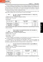
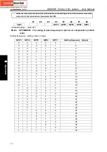
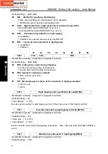
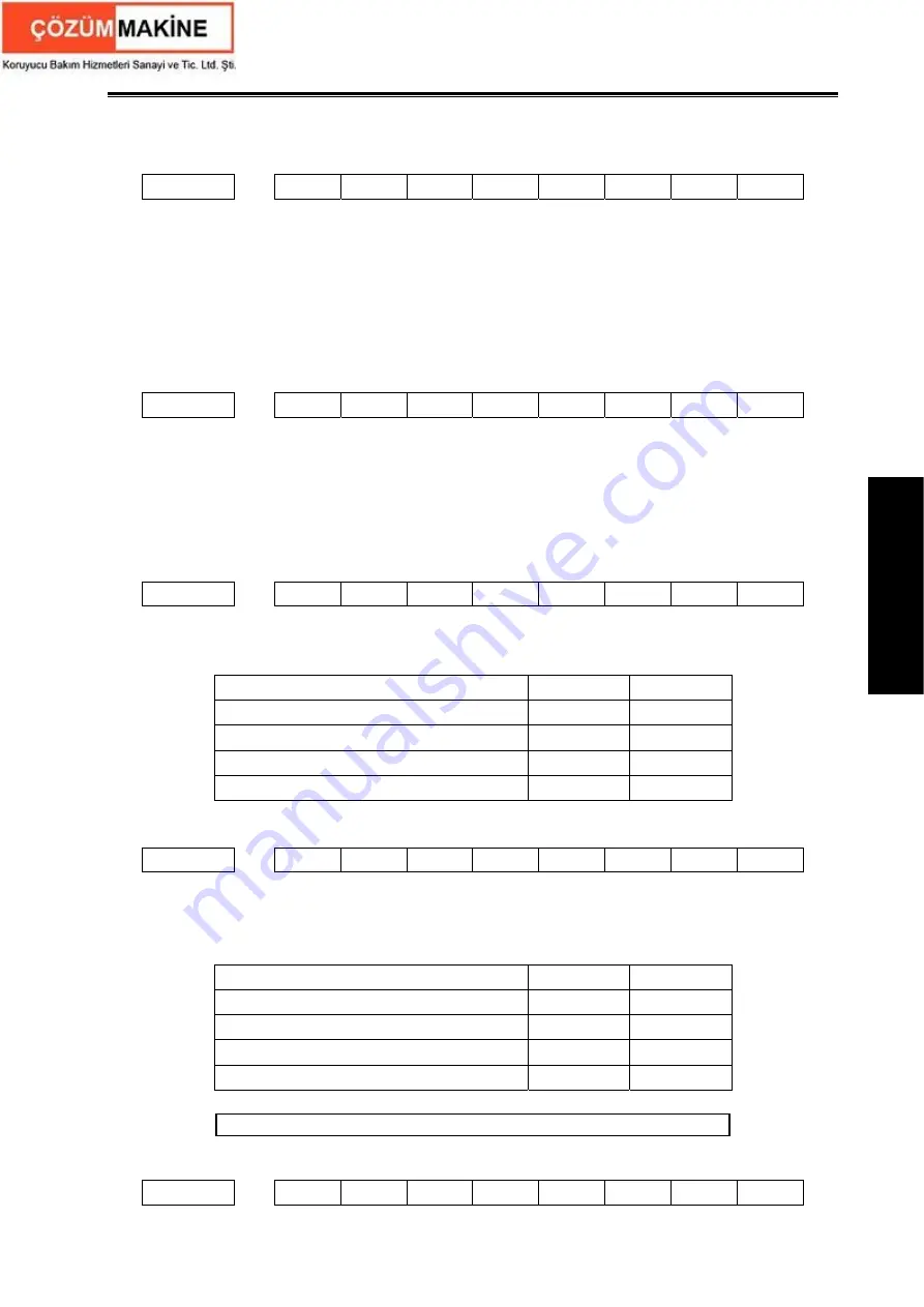
#7 #6 #5 #4 #3 #2 #1 #0
3700
NRF
『
Modification authority
』
: Equipment
『
Default Setting
』
: 0000 0000
#1 NRF The first move command(G00) after the spindle is switched to Cs axis
performs
0:Positioning after returning to the reference postion
1:Normal positioning
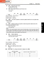
#7 #6 #5 #4 #3 #2 #1 #0
3705
EVS
#4 EVS When the spindle control function is used, S codes and SF are (spindle analog
output or spindle serial output)
0: Not output for an S command
1: Output for an S command
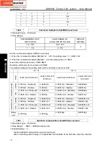
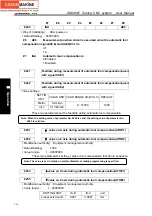
#7 #6 #5 #4 #3 #2 #1 #0
3706
PG2
PG1
『
Default Setting
』
: 0000 0000
#0, #1 PG2 and PG1 Gear ratio between the spindle and the position encoder.
Gear ratio=spindle speed/position encoder speed
Gear ratio
PG2
PG1
×1 0
0
×2 0
1
×4 1
0
×8 1
1
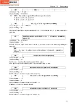
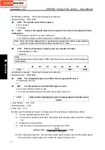
#7 #6 #5 #4 #3 #2 #1 #0
3707
P22
P21
『
Default Setting
』
: 0000 0000
#0, #1 P22 and P21 Gear ratio between the spindle and the second position encoder.
Gear ratio= spindle speed/position encoder speed
Gear ratio
P22
P21
×1 0
0
×2 0
1
×4 1
0
×8 1
1
Note: The parameter is valid only when multi-spindle control.
#7 #6 #5 #4 #3 #2 #1 #0
3708
TSO
SAT
SAR
Summary of Contents for 988T
Page 6: ...GSK988T Turning CNC System User Manual VI ...
Page 14: ...GSK988T Turning CNC System User Manual XIV ...
Page 15: ...Chapter 1 Programming Fundamentals 1 Ⅰ Programming Ⅰ PROGRAMMING ...
Page 16: ...GSK988T Turning CNC System User Manual 2 Ⅰ Programming ...
Page 194: ...GSK988T Turning CNC System User Manual 180 Ⅰ Programming ...
Page 195: ...Chapter Ⅰ Overview 181 Ⅱ Operation Ⅱ OPERATION ...
Page 196: ...GSK988T Turning CNC System User Manual 182 Ⅱ Operation ...
Page 217: ...Chapter Ⅲ Windows 203 Ⅱ Operation ...
Page 267: ...Chapter Ⅲ Windows 253 Ⅱ Operation Fig 3 51 Fig 3 52 ...

