DA98D User Manual
18
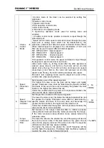
CN1-32
CN1-33
Common
edge of
Output
terminal
DG
Common
edge
Earthling common edge of control signal output
terminal (excluding CZ)
CN1-37
Z-Phase
output of
Encoder
CZ Type2
Output terminal for Z-phase of encoder
Output Z-phase pulse of servo motor’s
photoelectric code
CZ ON: Z-phase signal appears
CN1-26
Zero Speed
Clamping
ZSL Type1
ZSL ON: Servo driver is not under the control of
analog voltage, and zero speed is output.
ZSL OFF: servo driver is under the control of
analog voltage
CN1-36
CZCOM
Common edge of encoder’s Z-phase output
terminal
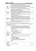
CN1-30 PULS+
CN1-15
Command
Pulse Input PULS-
Type3 P
CN1-29 SIGN+
CN1-14
Command
Pulse Input SIGN-
Type3 P
Input terminal for external command pulse
Note 1: the pulse input modes are set by PA14.
Mode of command pulse+ symbol;
Mode of CCW/CW command pulse
CN1-31
Shielding
Ground
Wire
FG
Earthling shielding terminal
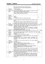
CN1-2
CN1-16
Analog
Ground
AGND
S
Analog
ground
CN1-17
Input
Simulation
Command
VCMD S
CN1-1
Input Analog
command
Ground
SG
Type4
S
Input analog -10V
Input resistance of 20K
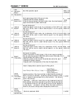
CN1-7
Positive
Terminal of
Hold Output
HOLD+ S/P
CN1-6
Negative
Terminal of
Hold
Output
HOLD-
Type2
S/P
Open-loop output of drain electrode, the
photoelectric coupler is open under normal
operation. ON is output
The power is off and the drive stops. When alarm
stops, the photoelectric coupler is closed. OFF is
output
CN1-27
Code disc
Pulse A+
PAOUT
+
S
CN1-12
Code disc
Pulse A-
PAOUT- S
CN1-28
Code disc
Pulse B+
PBOUT
+
Type5
Feedback output signal of encoder. The standard
is 2500/line
Output linear speed can be adjusted through
electronic gears of output PA 41 and PA42, e.g. if
the encoder has 2500 pulses per round, setting
PA41/42=4/5, then the A and B-phase signals
output from drive unit will be 2500 X
PA41/PA42=2000 pluses/round.
Summary of Contents for DA98D
Page 1: ...DA98D Digital AC Servo Drive Unit User Manual V5 00 ...
Page 15: ...DA98D User Manual 4 Fig 1 1 Appearance of Servo Drive unit 2 Servo motor appearance ...
Page 16: ...DA98D User Manual 5 Fig 1 2 Servo Motor Appearance ...
Page 23: ...DA98D User Manual 12 Fig 3 1 Standard Wiring for Position Control Mode AM26LS32 Receiver ...
Page 24: ...DA98D User Manual 13 Fig 3 2 Standard Wiring for Speed Control Mode AM26LS32 Receiver ...
Page 71: ...DA98D User Manual 60 Installation Dimension Drawing for BS 120 Model ...
Page 72: ...DA98D User Manual 61 Installment Dimension Drawing for BS 200 Model ...
Page 73: ...DA98D User Manual 62 Installment Dimension Drawing for BS 300 Model ...
Page 74: ...DA98D User Manual 63 Installment Dimension Drawing for BD 80 Model ...
Page 75: ...DA98D User Manual 64 Installment Dimension Drawing for BD 120 Model ...


