DA98D User Manual
53
Chapter Eight Product Specifications
●
Servo drive unit must be selected to match the servo motor. This manual describes matched
specifications on GKS SJT series and ST series of products.
●
Servo motor description. The user shall make a clear indication in the order if he or she needs to
select servo motor of other manufacturers.
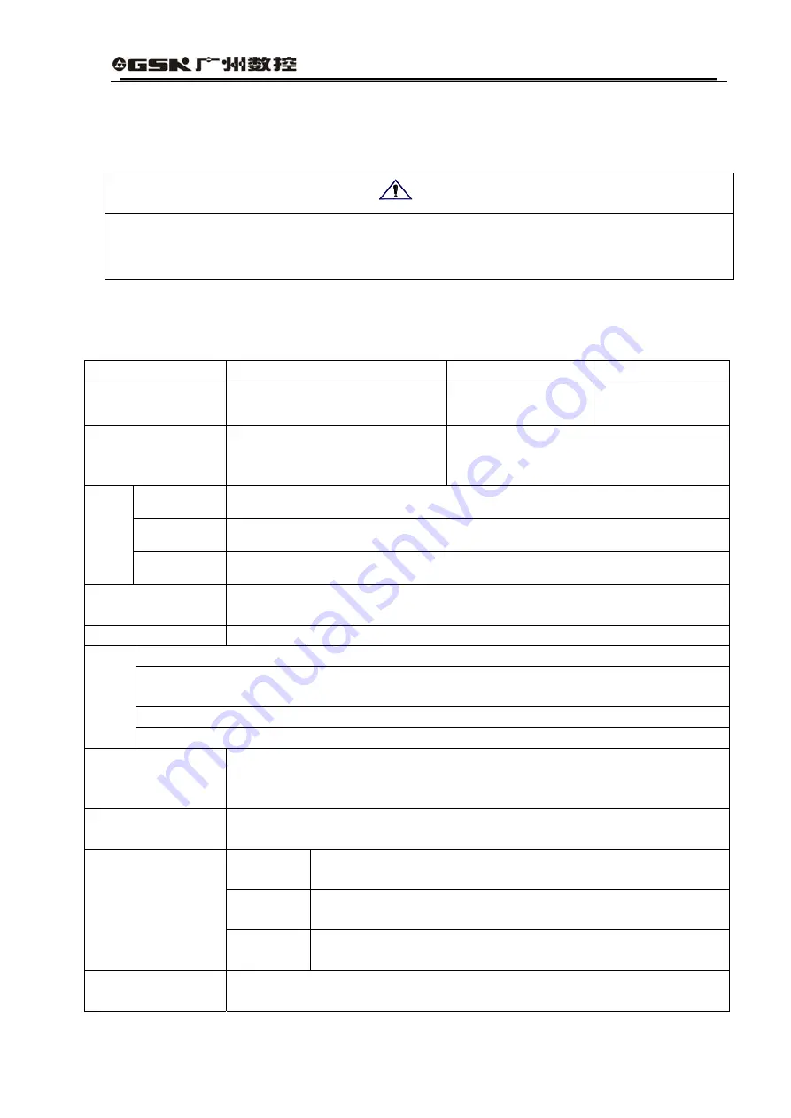
8.1 Driver Specifications
Table 8.1 Servo Driver Specifications
Output Power(kW)
0.4
~
0.8 1.0
~
1.5 1.7
~
2.3
Rated Torque of
Motor (Nm)
2
~
4 4
~
10 6
~
15
Input Voltage
Three Phases or Single Phase
AC220V
-15%
~
+10% 50 Hz /60Hz
Three-phase AC220V
-15%
~
+10% 50 Hz /60Hz
Temperature Operaton:0
℃
~
55
℃
Storage:-20
℃
~
80
℃
Humidity
Less than 90%(no dew condensation)
Operatio
n
Environment
Vibration
Less than 0.5G(4.9m/S2),10
~
60 Hz(non-continuous operation)
Control Mode
①
Position Control
②
Speed Control
③
Speed Trial Operation JOG
④
Operation
⑤
Open-loop Operation
Regenerative Brake Built in
Speed Frequency Response:200Hz or more
Speed Wave Frequency:
<
±0.03(load 0
~
100%):
<
±0.02(power supply-15%
~
+10%)(the
value shall correspond to rated velocity)
Speed Ratio:1:5000
Control
Features
Pulse Frequency:
≤
500kHz
Control Input
①
Servo on;
②
Alarm Clearance ; CCW
③
Drive Stopping; CW
④
Drive
Stopping;
⑤
Error Meter Clearance/Speed Choice1;
⑥
Command Pulse
Inhibiting/Speed Choice2; CCW
⑦
Torque Limiting; CW
⑧
Torque Limiting.
Control Output
①
Servo Ready for Output;
②
Servo Alarm Output;
③
Positioning Completing
Output/Speed Completing Output.
④
Hold Output
Input
Forms
①
Pulse+Symbol; CCW
②
Pulse/CW Pulse;
Electronic
Gear Ratio
1
~
32767/1
~
32767
Position Control
Feedback
Pulse
10000 Pulses/Round
Speed Control
1) Analog Speed Control Mode: +-10V Voltage; Input Impedance 20K
2) Electronic Gear Ratio: 1-1/255
Attention
Summary of Contents for DA98D
Page 1: ...DA98D Digital AC Servo Drive Unit User Manual V5 00 ...
Page 15: ...DA98D User Manual 4 Fig 1 1 Appearance of Servo Drive unit 2 Servo motor appearance ...
Page 16: ...DA98D User Manual 5 Fig 1 2 Servo Motor Appearance ...
Page 23: ...DA98D User Manual 12 Fig 3 1 Standard Wiring for Position Control Mode AM26LS32 Receiver ...
Page 24: ...DA98D User Manual 13 Fig 3 2 Standard Wiring for Speed Control Mode AM26LS32 Receiver ...
Page 71: ...DA98D User Manual 60 Installation Dimension Drawing for BS 120 Model ...
Page 72: ...DA98D User Manual 61 Installment Dimension Drawing for BS 200 Model ...
Page 73: ...DA98D User Manual 62 Installment Dimension Drawing for BS 300 Model ...
Page 74: ...DA98D User Manual 63 Installment Dimension Drawing for BD 80 Model ...
Page 75: ...DA98D User Manual 64 Installment Dimension Drawing for BD 120 Model ...

