- 24 -
STC 4-16 CT CI
154
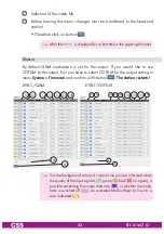
In column
Modulation
, select the desired kind of modulation of the indi-
vidual lines:
For QAM: QAM 16, 32, 64, 128, 256
For COFDM:
QPSK, 16 QAM, 64 QAM
—> The background colour
in column
Line
indicates an output data
overflow. In this case change the output settings or remove stations
from the data stream using the station filter.
—> COFDM: Since SAT transponders can transmit higher data rates
than DVB-T transponders, you must remove Services from the data
stream via the "Filter & CA" menu!
155
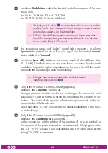
For exceptional cases and "older" digital cable receivers, in column
Spectrum
the spectral position of the user signal can be inverted (
invers
).
Factory default is "
normal
".
156
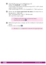
In column
Level [dB]
, balance the output levels of the different lines
(0…-10dB). Therefore measure and note down the output level of each
modulator. Adjust the higher output levels to the output level of the modu-
lator with the lowest output level incrementally.
—> Changes must be transmitted to the head-end station!
Therefore click on button
.
158
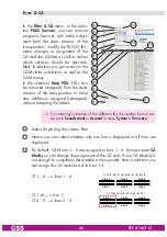
Only if the RF output is set to COFDM (page 43):
Setting of the
Code rate
- column
CR
During a transmission data can be lost or changed. To recover this data
redundancy is added to the signal to be transmitted (forward error cor-
rection). The factor of the quantity of redundancy contained in the bits
transmitted is called code rate.
Using the setting "C7/8" you can get the highest output data rate at low-
est redundancy.
159
Only if the RF output is set to COFDM (page 43):
Setting of the
Guard interval
- column
GI
In this column you set the relation of the duration of the user symbols to
the duration of the guard intervals to be transmitted. A high guard inter-
val, e.g. "G1/4" causes a low output data rate. For cable networks the
setting "G1/32" is adequate.

