- 7 -
HDTA 614 C ASI
g
ener al
The cassette is equipped with four channel strips ("
A
" … "
D
"). The channel
strips consist of the digital tuners, the digital signal preparation units and the
output converters.
For channel strips A/B resp. C/D adjacent channel setting is fixed.
The channel strips are indicated in the head-end station display with "
Bx …A
"
… "
Bx …D
". Using adequate CA modules scrambled channels can be de-
scrambled via tuner "
A
" and "
C
".
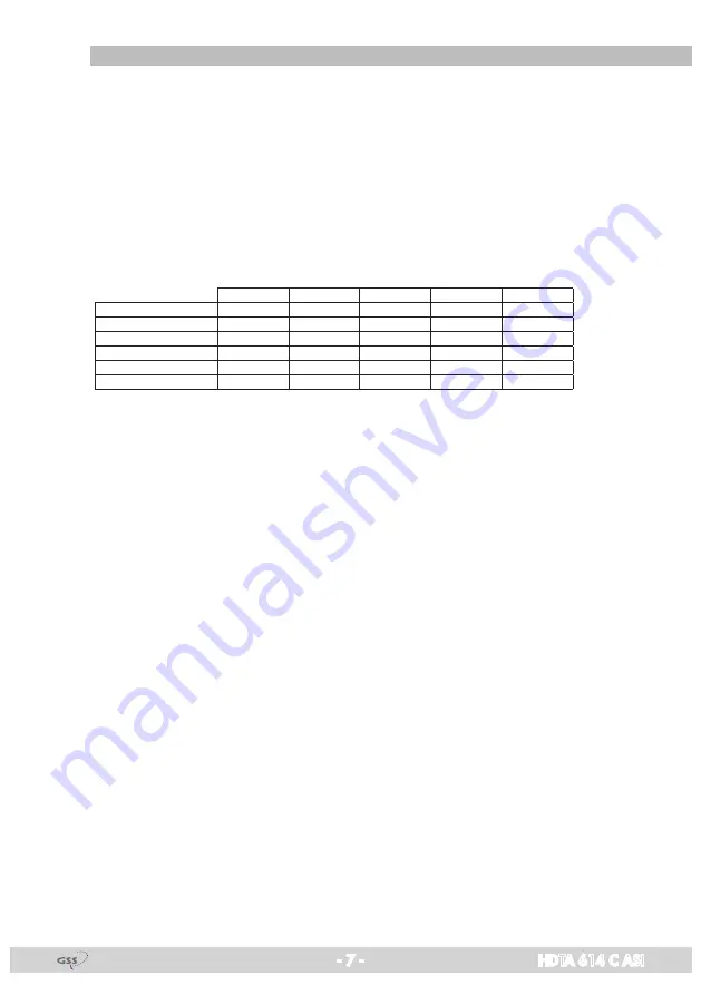
As signal source of the channel strips, tuners or the ASI input can be selected
according to the table below:
Line A
Line B
Line C
Line D
CA
0xASI
OFF
Tuner A
Tuner B
Tuner C
Tuner D
2
1xASI
D
Tuner A
Tuner B
Tuner C
ASI
2
2xASI
B/D
Tuner A
ASI
Tuner C
ASI
2
2xASI
C/D
Tuner A
Tuner B
ASI
ASI
1
3xASI
B/C/D
Tuner A
ASI
ASI
ASI
1
4xASI
A/B/C/D
ASI
ASI
ASI
ASI
0
The control of the cassette takes place via the control unit of the head-end station.
Four LEDs provide an indication of the SAT IF input signal quality based on
their colour and indicate if the respective channel strip is switched on (LED il-
luminates) or off. If there is an overflow of the output data rate, the correspond-
ing LED blinks red/green.
The integrated TPS module (Transport Stream Processing) processes the data
of the transport streams.
Channel as well as frequency setting is possible for modulators "
A
" and "
C
".
The modulators "
B
" and "
D
" work at a spacing of + 8 MHz to modulators"
A
"
and "
C
". Herein only frequency setting (frequency spacing of channel strips
"A <–> B" and "C <–> D") is possible to reduce the bandwidth at signals of
low data rates.
The QAM modulated RF output signals are sent through the RF output of the
cassette to the output collector. The common output level of the channel strips
can be set at the output collector.
When the head-end station is switched on, the two-line LC display shows the
software version of the control unit. To operate this cassette the software ver-
sion of the control unit must be "
V 44
" or higher. You can find the current op-
erating software for the control unit and the cassette, the software "
BE-Flash
"
and the current assembly instructions on the website "
www.gss.de/en
".
The cassette is (with exception of STC 332) intended for use in the
STANDARD LINE head-end stations.


