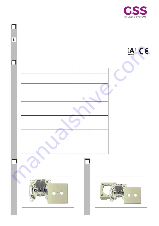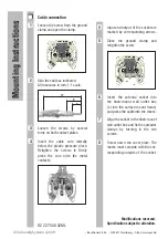
Antenna sockets for common antenna systems or widerband communication
systems.
The antenna sockets indicated below comply with the DIN Standards 45 330, 45 325 (IEV) and
DIN EN 50083-2/-4. Through fitting the 75-
Ω
terminal resistor ORT 01 into
the output connector, the antenna sockets can also be used as final trunk
line sockets.
Loss values
Flush mounting
Mount the antenna socket into a 55 wall
outlet box. Fit the cover plate ORC 02.
Surface mounting
For this, use the surface-mount frame
ORF 03 and the cover plate ORC 02.
ANTENNA SOCKETS
OR 02, OR 09, OR 11
Type
OR 02
OR 09
OR 11
OR 15
OR 20
Order
G.AC
G.AC
G.AC
G.AC
G.AC
Number
72-00
68-00
69-00
70-00
71-00
Transmission
loss
5 – 470 MHz
––
2.5 dB
0.9 dB
0,8 dB
0,5 dB
470 – 862 MHz
––
2.8 dB
1.1 dB
1,0 dB
0,8 dB
TV output
loss
5 – 862 MHz
2,4 dB
9 dB
12 dB
15,0 dB
20,0 dB
RF output
loss
5 – 139 MHz
6,0 dB
12 dB
15.5 dB
18,0 dB
22,0 dB
Directivity loss
5 – 862 MHz
––
> 25 dB
> 30 dB
> 33 dB
> 38 dB
Back-flow
loss
5 – 862 MHz
> 14 dB
> 14 dB
> 18 dB
> 15 dB
> 15 dB


