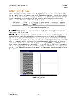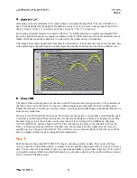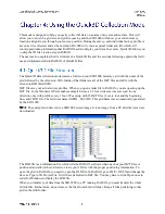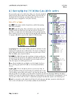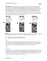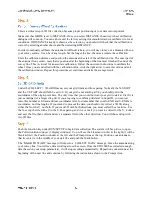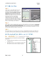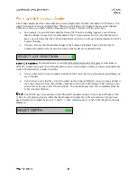
So, to sum up: each grid you collect is a separate folder. Inside that folder are all of your radar data lines
(DZT files). Also inside that folder is the B3D file which you will open in RADAN. Once RADAN reads
that B3D file, it will know which of your data lines to put where.
You must keep that B3D file and all
of you data files together in the same grid folder.
Collecting data for 3D imaging is easiest when you have a guide grid laid out to follow. You should lay
out a grid with chalk, paint, ropes, or some other method. Your grid can be any size, but your data quality
will be much better if you make sure that your grid corners are square. Your grid itself does not have to be
a square, it can be a rectangle, or can be irregularly shaped, but if you follow the tips below, you will save
yourself a lot of trouble.
If you are scanning in one direction only with a normal profile order (one direction only), you need
the grid edge that you start your profiles from (the baseline) to be straight. We understand ‘one
direction only’ to mean scanning along only the X or the Y axis, but not both. A ‘normal’ profile
order is one where you are collecting data along your profile in one direction. In other words, you
start at the baseline, collect your data until the end of the line, pick up your system and move it back
to the baseline to collect the next profile in the same direction. This is different from zig-zag where
you are simply turning around and collecting the next data file in the opposite direction from the
previous. If you are collection with a zig-zag order, both the start and finish baselines should be
straight.
Your grid can be irregular, but as long as the line that your profiles start from is straight, the
RADAN software will have no problem lining things up.
Make sure that your grid corners are right angles and that your grid lines are actually perpendicular
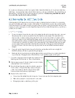
to your baseline. The graphic below illustrates how to put together a square, 10×10 grid.
Locate the origin point (0,0) and pull a tape measure 10 to
find the point 10,0 (blue line: a). This is your baseline.
Pull one tape measure 10 from 0,0 (line b) to 0,10. Pull the
other one from 10,0 to 0,10 (line c).
Move both tapes together so that 10 on line b connects to
14.14 on line c. The point that they connect is the grid
corner. You will know that the corner at 0,0 is square
because this method produces a right triangle.
Repeat for the corner 10,10.
You can use this method for grids of any size. You can also use this for rectangular grids.
Make sure to assign X to one axis and Y to the other.
Photograph or make a sketch map of the grid.

