background image

4.2: Mechan cal and Electr cal Assembly

 4.2.1: Return to Factory Sett ngs

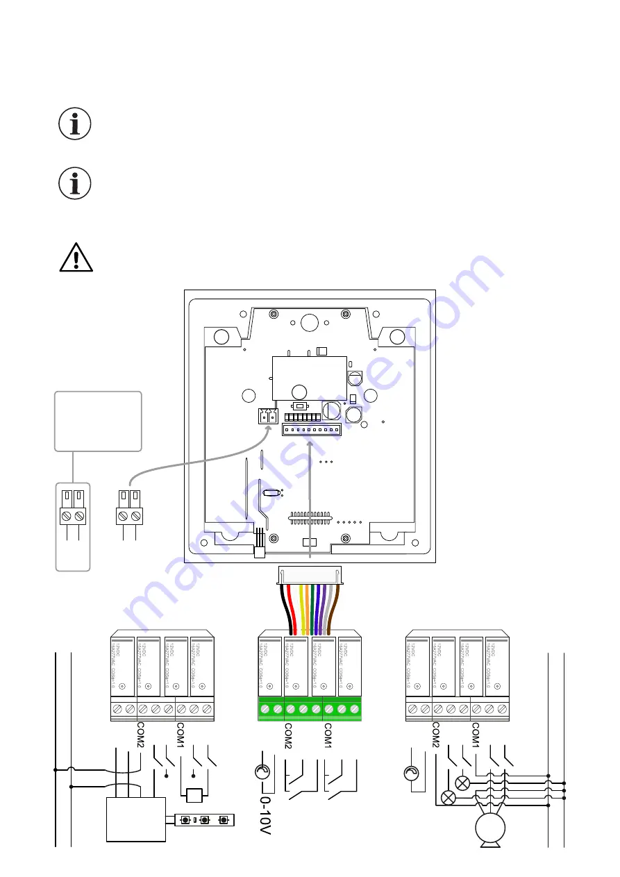
 4.2.2: Electr cal Assembly

L  N

The relay group that can be mounted and d smounted to the back of the dev ce 

enables you to turn on/turn off the dev ce or d m the fixtures w th 0-10VDC output

L

 : 

 Phase

N

 : 

Neutral

Q

 : 

D g tal Output

P n

COM

 : 

Common 

contact po nt

+,-

 : Pos t ve, Negat ve 

poles

M

 : 

Curta n, Bl nder


Motor

K

 : 

Comb  bo ler 

thermostat connect on

B

 : Mount ng

apparatus bear ng

The dev ce w ll return the factory sett ngs when the Reset button  s pressed and 
held for 10 seconds. The button  s represented w th “B” letter  n the draw ng.

S nce relays have a common COM connect on when the relay  s connected to the 
comb  bo ler, leave Q2 output empty  f connected to Q1 and leave Q4 output empty 

f connected to Q3.

+  -

12V

D C supply
p r o d u c t 
connect on 
s t r u c t u r e

6

from the Smart Touch Panel. The relay can res st up to 277VAC 16A  nrush 100A and offers
long l fet me w thout bond ng.

M

L   N

L   N

K

Q1

Q2

Q3

Q4

Q1

Q2

Q3

Q4

DIM+

DIM-

DIM+

DIM-

RELA

Y1

RELA

Y2

RELA

Y3

RELA

Y4

DIM+

DIM-

D

I

M

-

D

I

M

+

LED Dr ver

240VAC

LED Str p

Vo+
Vo-

A

A

B

Summary of Contents for inohom STP1710

Page 1: ...Smart Touch Panel STP1710 V1 0 inohom USER MANUAL EN Smart Life Solutions...

Page 2: ...1 Technical Details 3 2 Technical Drawing 4 Installation 4 1 Before Installation 4 2 Mechanical and Electrical Assembly 4 2 1 Return to Factory Settings 4 2 2 Electrical Assembly 4 2 3 Mechanical Ass...

Page 3: ...ct ons w ll be changed Do not operate the dev ce w th wet or mo st hands to avo d electr c shock r sk Do not make any changes on th s dev ce that are not spec ed n the user manual Do not leave the dev...

Page 4: ...ma n page Th s panel has programmable 20 menu pages and you can add 4 controls on each page Sw tch ng between pages s done w th the buttons below There are black and wh te glass colour opt ons Output...

Page 5: ...damage r sk Do not power on the dev ce before all the connect ons are completed Check the dev ce user manual to create a secure connect on Do not make any connect ons other than the connect ons spec...

Page 6: ...The dev ce w ll return the factory sett ngs when the Reset button s pressed and held for 10 seconds The button s represented w th B letter n the draw ng S nce relays have a common COM connect on when...

Page 7: ...ng screw the ground Use the mount ng apparatus n the box for mount ng Please use the correspond ng holes of mount ng apparatus to mount sw tch case Make sure that the apparatus s perpend cularly mount...

Page 8: ...Panel can w relessly commun cate w th other nohom products and can learn and sw tch output state values of other products You can tr gger ts own when used w th relay or relays on RL 1710 CCM176X or N...

Page 9: ...page To turn t o any of the lower buttons must 6 DESCRIPTIONS 6 1 Button Funct ons 6 2 Screen Menu Descr pt ons Th s operat on s completed by tra ned techn cal personnel n comm ss on ng program Go Bac...

Page 10: ...A C ENERGY OFF A C FLAP ANGLE SETTING SCENARIO ACTIVATION OPEN AND CLOUDY WEATHER RAINY WEATHER SNOWY WEATHER IR A C TURN ON OFF CONTROL A C FAN SPEED SETTING CLOUDY WEATHER MISTY WEATHER SUNNY WEATH...

Page 11: ...anel nterface s used to dent fy the related dev ce The LEDs on the dev ce w ll bl nk w th 1 second nterval when pressed FIND button and press STOP button when the dev ce s found Then sett ng parameter...

Page 12: ...the trademarks of the r respect ve owners The domest c product on logo on all the products show that themanufactur ng and software are 100 completed n Turkey The company has ISO 9001 Qual ty Managemen...

Reviews: