Chapter 6 Specification of Parameters GK600 User Manual
- 130 -
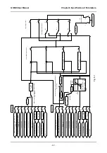
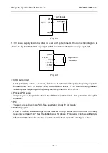
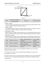
Fig. 6-7
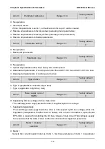
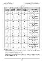
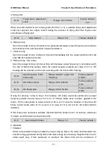
b0-07
Computation of master
and auxiliary FREQ
Range: 0~3
Factory default: 0
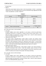
0: auxiliary
The sum of master and auxiliary frequency is taken as frequency command. Output result is
subject to limitation of upper and lower limit frequency.
1: Master - auxiliary
The difference between master and auxiliary frequency is taken as frequency command.
Output result is subject to limitation of upper and lower limit frequency.
2: Max {master, auxiliary}
Master frequency or auxiliary frequency (whichever has a larger absolute value) is taken as
frequency command. Output result is subject to limitation of upper and lower limit frequency.
3: Min {master, auxiliary}
Master frequency or auxiliary frequency (whichever has a smaller absolute value) is taken as
frequency command. Output result is subject to limitation of upper and lower limit frequency.
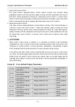
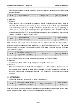
b0-08
Maximum frequency
Range: Upper limit frequency
~600.00Hz
Factory default:
50.00Hz
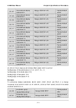
b0-09
Upper limit frequency
Range: Lower limit frequency ~
maximum frequency
Factory default:
50.00Hz
b0-10
Lower limit frequency
Range: 0.00Hz ~ upper limit
frequency
Factory default:
0.00Hz
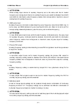
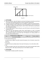
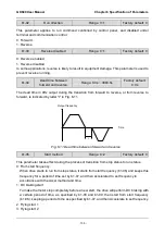
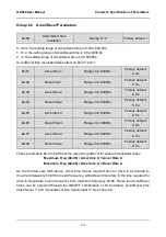
Maximum frequency of b0-08 is the maximum allowable output frequency of drive and is
indicated by fmax in the figure.
B0-09 upper limit frequency is the user-defined maximum allowable run frequency and
represented by fH in Fig. 6-8.
B0-10 lower limit frequency is user-defined minimum allowable run frequency and marked with
fL in Fig. 6-8. In Fig. 6-8, fN represents rated frequency of motor while VN means the rated
voltage of motor.
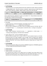
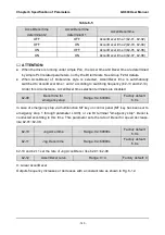
0
PID
输出
主给定值
×(b0-06)
频率输出
最大值
Maximum value
PID output
Frequency output
Master command
value × (b0-06)

