Chapter 6 Specification of Parameters GK600 User Manual
- 150 -
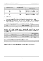
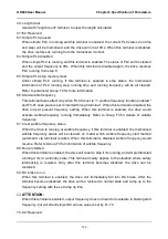
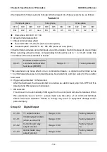
20: Accel/Decel time determinant 2
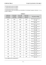
Accel/Decel time determinant 1~2 can realize at most 4 Accel/Decel time settings through
combination of different statuses as shown in Table 6-8. Accel/Decel time can be switched
via different combinations during run.
Table 6-8
Accel/Decel time
determinant 2
Accel/Decel time
determinant 1
Accel/Decel time
OFF
OFF
Accel/Decel time 1(b2-01,
b2-02)
OFF
ON
Accel/Decel time 2(b2-03,
b2-04)
ON
OFF
Accel/Decel time 3(b2-05,
b2-06)
ON
ON
Accel/Decel time 4(b2-07,
b2-08)
ATTENTION:
The selection of Accel/Decel time 1~4 is not determined by digital input terminals when
the drive is running under simple PLC. See parameter Group F2 for details. When
broken-line Accel/Decel is enabled, Accel/Decel time is automatically switched to
Accel/Decel time 1 and 2 according to switching frequency (b2-13 and b2-14). In this case,
Accel/Decel time determinant terminals are disabled.
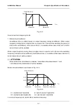
21: Accel/Decel disabled (ramp stop not inclusive)
When "Accel/Decel disabled" terminal is enabled, the drive maintains the present output
frequency and no longer responds to the change of frequency setting. But it will still perform
ramp-down stop when receiving stop command. This terminal is disabled during normal
ramp-down stop.
22: External fault input
This terminal is used to input the fault signal of external equipment, making the drive to
perform fault monitoring and protection. When external fault signal is received, the drive
shall display "PEr" and stop running.
23: Fault reset (RESET)
When the drive fault occurs, this enabled terminal will reset the fault. This function is the
same with RESET key on control panel.
24: Pulse input (valid only for X6/DI)
This is valid only for digital input terminal X6/DI. This terminal receives pulse signal as
frequency setting. Refer to C2-24~C2-27 for the relationship between pulse signal and
frequency setting.
When pulse input is selected as the frequency setting, X6/DI terminal must be set to "pulse

