GK600 User Manual
Chapter 6 Specification of Parameters
-
159 -
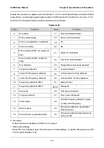
Define the functions of digital output terminals Y1 & Y2, control board relay and option board
relay. When used as high-speed pulse output, Y2/DO terminal's function are not set in C1-01
but in C3-02. Output terminal function selections are as follows:
Table 6-14
Value
Function
Value
Function
0
No output
17
Drive overheated alarm
1
Drive undervoltage
18
Zero-current detection
2
Drive run preparation completed
19
X1
3
Drive is running
20
X2
4
Drive running at 0Hz (no output at
stop)
21
Motor 1/2 indication
5
Drive running at 0Hz (output at
stop)
22
Set count value attained
6
Run direction
23
Designated count value attained
7
Frequency attained
24
Length attained
8
Upper limit frequency attained
25
Consecutive run time attained
9
Lower limit frequency attained
26
Accumulative run time attained
10
Frequency detection FDT1
27
Brake control
11
Frequency detection FDT2
28~29 Reserved
12
Reserved
30
PLC step completed
13
Torque restricted
31
PLC cycle completed
14
Fault output
32
Wobble frequency attains to upper
or lower limit frequency
15
Alarm output
33
Frequency attains to upper/lower
limit frequency
16
Drive (motor) overloaded alarm
34
Frequency attains target-frequency
set by C2-29
0: No output
Output terminal is disabled, and there is no output.
1: Drive undervoltage
When DC bus voltage is lower than the level of undervoltage, it outputs ON signal and LED
control panel displays "LoU".

