Chapter 6 Specification of Parameters
GK600 User Manual
- 204 -
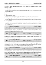
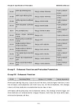
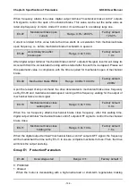
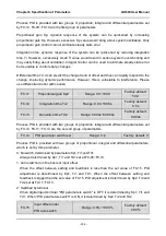
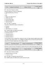
F0-00
PID setting
Range: 0~5
Factory default: 0
Select the setting source of PID control.
0: F0-01 digital setting
1:AI1
2:AI2
3: EAI (on IO option board)
4: X6/DI pulse input
5: Communication
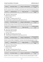
F0-01
PID digital setting
Range: 0.0%~100.0%
Factory default:
50.0%
When F0-00 is set to 0, this parameter value is taken as the set value of PID.
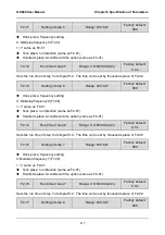
F0-02
PID feedback
Range: 0~8
Factory default: 0
Select the feedback source of PID control.
0:AI1
1:AI2
2: EAI (on IO option board)
3:AI1+AI2
4:AI1-AI2
5:max
{
AI1
,
AI2
}
6:min
{
AI1
,
AI2
}
7: X6/DI pulse input
8: Communication
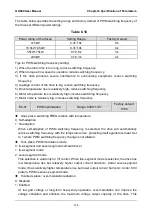
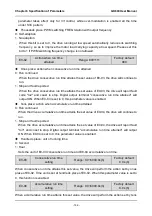
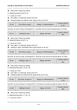
F0-03
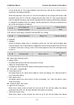
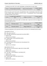
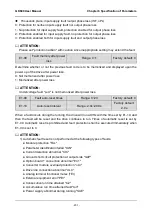
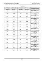
PID adjustment
Range: 00~11
Factory default: 11
Ones place: output frequency
0: Must be the same direction as the set run direction
When PID frequency output direction is opposite to the rotary set direction, PID output is 0.
1: Opposite direction allowed
PID frequency output direction can be opposite to the rotary set direction, and PID output
performs normally.
Tens place: integration selection
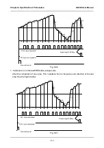
0: Integral continued when frequency attains upper/lower frequency
Under PID control, when output frequency attains upper/lower limit of frequency or
parameter value of F0-23 (maximum frequency if it is opposite to the rotary set direction), PID
integral continues. This mode requires longer time of quitting saturation.
1: Integral stopped when frequency attains upper/lower limit
Under PID control, when output frequency attains upper/lower limit of frequency or
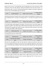
parameter value of F0-23 (maximum frequency if it is opposite to the rotary set direction), PID

