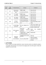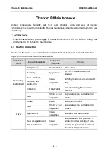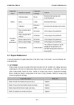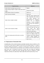
GK600 User Manual Appendix Communication Protocol
- 253 -
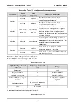
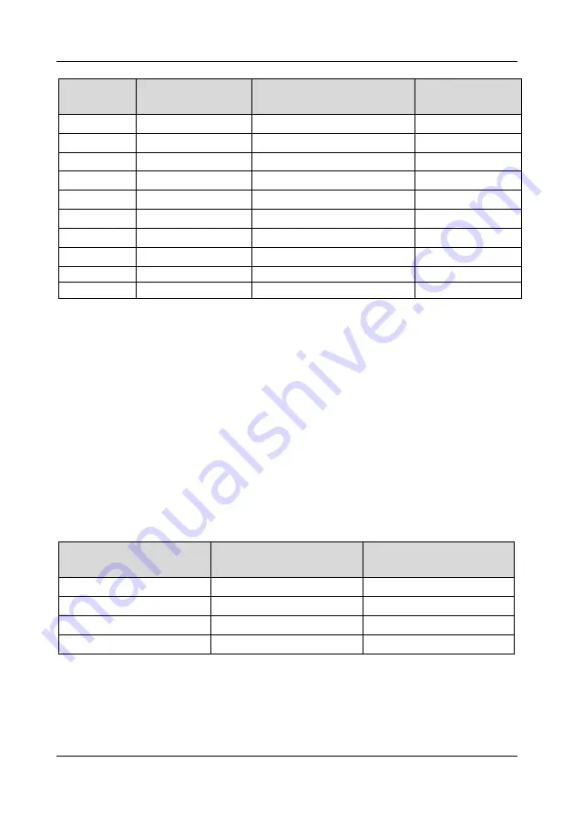
Parameter
group
Mapping register
address, high byte
Parameter group
Mapping register
address, high byte
C3
0x08
H0
0x1A
C4
0x09
H1
0x1B
d0
0x0A
H2
0x1C
d1
0x0B
L0
0x1D
d2
0x0C
L1
0x1E
d3
0x0D
U0
0x1F
d4
0x0E
U1
0x20
d5
0x0F
U2
0x21
d6
0x10
Drive control parameter group
0x62
E0
0x11
Drive status parameter group
0x63
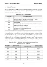
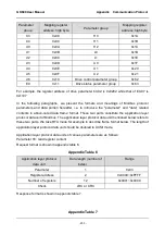
For example, the register address of drive parameter b0-02 is 0x0202
while that of E0-07 is
0x1107.
In the following paragraphs, we present the formats and meanings of Modbus protocol
parameters and data portion hereafter, i.e. to introduce the "parameter" and "data" related
contents in above-noted data frame format. These two parts constitute the application layer
protocol data unit of Modbus. The application layer protocol data unit mentioned below refers to
these two parts. We take RTU mode for example to describe frame format below. The length of
application layer protocol data unit should be doubled in ACSII mode.
Application layer protocol data units of various parameters are as follows:
Parameter 03: read register content
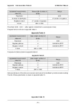
Request format is shown in appendix table 6.
Appendix Table 6
Application layer protocol
data unit
Data length (number of
bytes)
Range
Parameter
1
0x03
Register address
2
0x0000~0xFFFF
Number of registers
12
0x0001~0x000C
Check
LRC or CRC
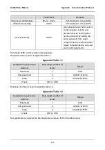
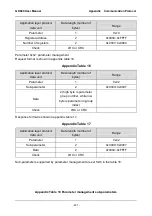
Response format is shown in appendix table 7.
Appendix Table 7

