Chapter 3 Installation and Wiring GK600 User Manual
- 44 -
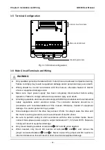
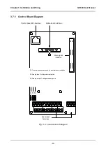
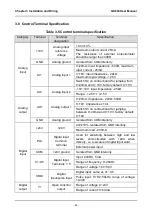
3.8 Control Terminal Specification
Table 3-5 Control terminal specification
Category
Terminal
Terminal
designation
Specification
Analog
input
+10V
Analog input
reference
voltage
10.3V ±3%
Maximum output current 25mA
The resistance of external potentiometer
should be larger than 400Ω
GND
Analog ground
Isolated from COM interiorly
AI1
Analog input 1
0~20mA: input impedance - 500Ω, maximum
input current - 25mA
0~10V: input impedance - 22kΩ,
maximum input voltage - 12.5V
Switch S2 on control board for jumping from
0~20mA and 0~10V, factory default: 0~10V
AI2
Analog input 2
-10V~10V: input impedance - 25kΩ
Range: -12.5V~+ 12.5V
Analog
output
AO1
Analog output 1
0~20mA: impedance - 200Ω~500Ω
0~10V: impedance ≥ 10k
Switch S3 on control board for jumping
between 0~20mA and 0~10V, factory default:
0~10V
GND
Analog ground
Isolated from COM interiorly
Digital
input
+24V
+24V
24V±10%, Isolated from GND interiorly
Maximum load - 200mA
PLC
Digital input
Common
terminal
Used for switching between high and low
levels, short-circuited with +24V when
delivery, i.e. low value of digital input valid
External power input
COM
+24V ground
Isolated from GND interiorly
X1~X5
Digital input
Terminals 1~5
Input: 24VDC, 5mA
Range of frequency: 0~200Hz
Range of voltage: 10V~30V
X6/DI
Digital
input/pulse input
Digital input: same as X1~X5
Pulse input: 0.1Hz~50kHz; range of voltage:
10-30V
Digital
output
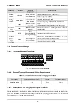
Y1
Open collector
output
Range of voltage: 0~24V
Range of current: 0~50mA

