Chapter 1 Installation
MUST400_User manual_EN_REV02 User Manual
15
1.6 Power Cables
Design the cables according to the descriptions in this section and local regulatory wiring standards, and the
environmental conditions (temperature and physical support media) should be taken into consideration.
Refer to IEC60950-1 Table 3B Cabling.
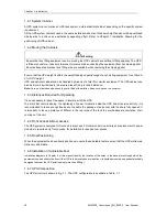
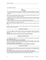
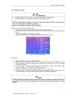
WARNING
FAILURE TO FOLLOW ADEQUATE EARTHING PROCEDURES CAN RESULT IN EMI, ELECTRIC SHOCK HAZARD,
OR RISK OF FIRE, IF AN EARTH FAULT OCCURS.
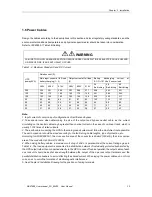
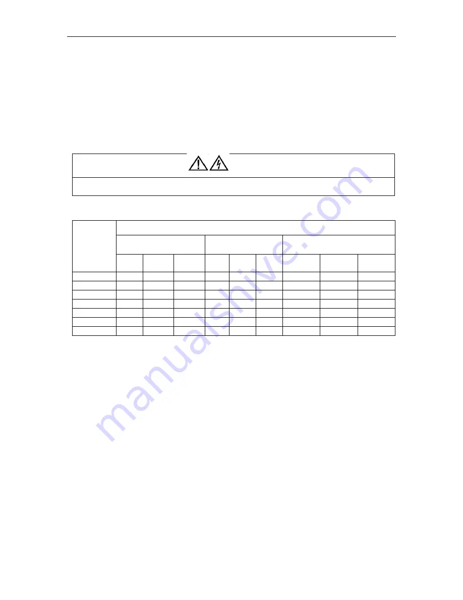
Table.1- 2: Maximum Steady AC and DC Current
UPS
power(KVA)
Rated current (A)
Main input current at full load
battery charging (1
,
2)
Output current at full load
(2)
Battery
discharging
current
at
E.O.D=1.67V/cell, no overload
380V
400V
415V
380V
400V
415V
36
Batt./string
38
Batt./string
40
Batt./string
200
306
291
280
303
288
277
468
443
421
120
184
175
168
182
173
166
281
266
253
100
153
146
140
152
144
139
234
222
211
60
92
88
84
91
87
83
142
133
127
40
62
59
56
61
68
56
94
89
85
30
46
44
42
46
44
42
71
67
64
20
31
29
28
31
34
28
47
45
43
Note:
1. Input current of common input configurations of rectifier and bypass
2. Take special care when determining the size of the output and bypass neutral cable, as the current
circulating on the neutral cable may be greater than nominal current in the case of non-linear loads, which is
usually 1.732 times of rated currents.
3. The earth cable connecting the UPS to the main ground system must follow the most direct route possible.
The earth conductor should be sized according to the fault rating, cable lengths, type of protection, etc.
According to AS/IEC60950-1, the cross section area of the conductor is 90mm2 (200kVA), the cross section
area of the conductor is 50mm2 (120KVA).
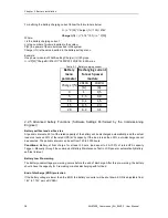
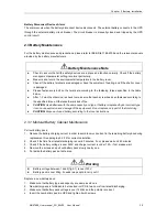
4. When sizing battery cables, a maximum volt drop of 4Vdc. is permissible at the current ratings given in
Table.1-2. The load equipment is connected to a distribution network of individually protected busbars fed by
the UPS output rather than connected directly to the UPS. In case off cabinet parallel, the output cable of each
ups rack unit should be kept at equal length between the output of the ups rack output terminals and the
parallel distribution busbars to avoid affecting the shared current. When laying the power cables, do not form
coils, so as to avoid the formation of electromagnetic interference.
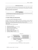
5. See Chapter 4 Installation Drawing for the positions of wiring terminals.
警告
危 险


