Chapter 3 Installation of UPS Rack System and System
30
MUST400_User manual_EN_REV02 User Manual
Chapter 3 Installation of UPS System and Parallel System
3.1 Overview
The single or parallel system should be installed according to the installation procedures of the UPS rack
module system and the requirements in this Chapter.
During the installation of the UPS, the local regulations for the field of application have to be respected.
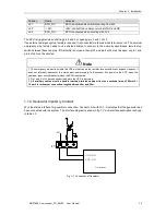
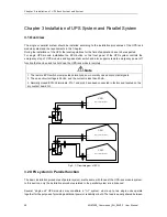
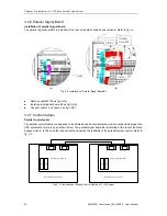
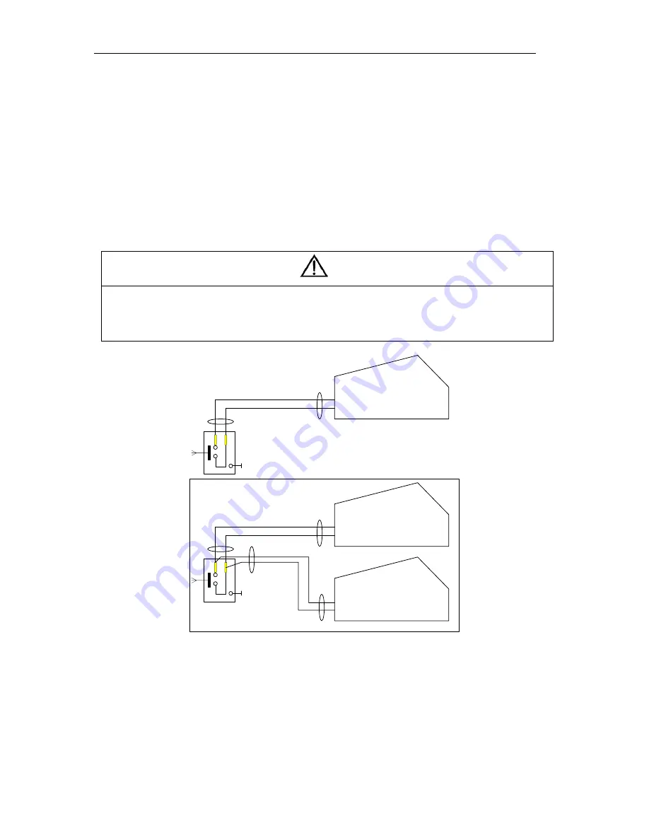
For single UPS module installation the EPO button on the front panel of the UPS system controls the
emergency stop of UPS modules and bypass static switch and also supports remote emergency power off
function that can be used to shut down the UPS rack module remotely.
Note
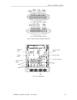
1. The remote EPO switch must provide normally open or normally closed dry contact signals.
2. The open circuit voltage is 24Vdc, and the current is less than 20mA.
3. Normally closed EPO-J4 terminals: Pin 1 and pin 2 have been connected in factory and located on the
dry contact board GJ.
UPS1
Dry contact board GJ
J4-2
J4-3
UPS1
Dry contact board GJ
J4-2
J4-3
UPS2
Dry contact board GJ
J4-2
J4-3
Fig.3- 1: Circuit diagram of EPO
3.2 UPS system in Parallel function
The basic installation procedures of parallel system are the same with those of the UPS rack module system.
In this section, only the installation procedures related to the parallel system are introduced.
Several “single unit” UPS modules may constitute a
“1+1” system, where up to two single units operate
together for the purpose of providing additional power or reliability or both. The load is equally shared between
警告
危 险

