Chapter 6 Operating Instructions
MUST400_User manual_EN_REV02 User Manual
49
1.
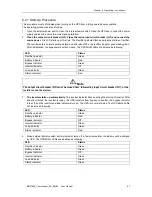
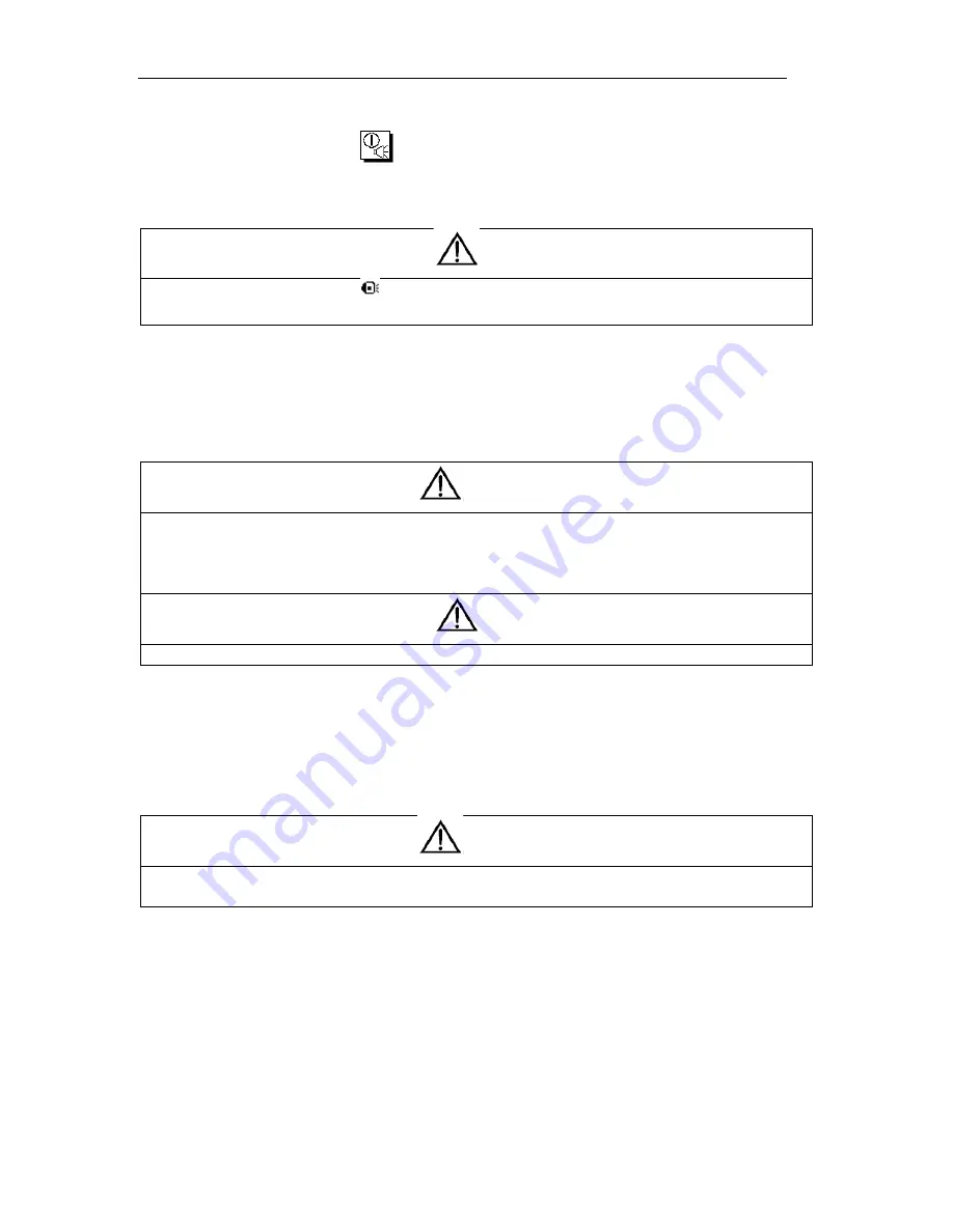
Press the “Tran Byp” menu in
on the right side of the LCD. The UPS Mimic indicator Inverter will
green flash and also the Status Indicator will turn red and will be accompanied by an audible alarm. The
load transfers to static bypass, and the inverter standby.
Note
Pressing the Alarm Silence button
cancels the audible alarm but leaves the warning message displayed
until the alarm condition is rectified.
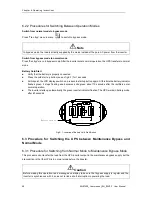
2. Open the UPS front door, close the maintenance bypass breaker (Q2) from OFF to ON position. The load
power supply is provided by the manual maintenance bypass.
3. Press EPO to make sure the battery charge current is 0A. Open the mains input breaker (Q1) and output
breaker (Q3), open the external battery breaker and internal battery breaker (if built-in battery modular
UPS)
Warning
If you need to maintain the module, wait for 10 minutes to let the DC bus capacitor fully discharge before
removing corresponding module.
When the maintenance bypass switch is in ON position, some part of the UPS circuit still has hazardous
voltage. Therefore, only qualified person can maintain the UPS.
Note
When the UPS is in maintenance bypass mode, the load is not protected against abnormal mains supply.
6.3.2 Procedure for Switching from Maintenance Mode to Normal Mode
1.
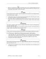
Close output breaker (Q3). Close mains input breaker (Q1). The LCD starts up at this time. The Rectifier
indicator flashes during the startup of rectifier. The rectifier enters normal operation state, and after about
20s, the rectifier indicator goes steady green. After initialization, the bypass static switch closes.
2.
Open the manual maintenance breaker (Q2).
Warning
Before opening the maintenance breaker (Q2), make sure that static bypass switch is working according
power flow displayed on LCD.
3.
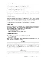
After about 60s, UPS transfers to inverter. Close external battery breaker and internal battery breaker
(for battery built-in cabinet).
警告
危 险
警告
危 险
警告
危 险
警告
危 险

