Chapter 1 Installation
12
MUST400_User manual_EN_REV02 User Manual
(c)
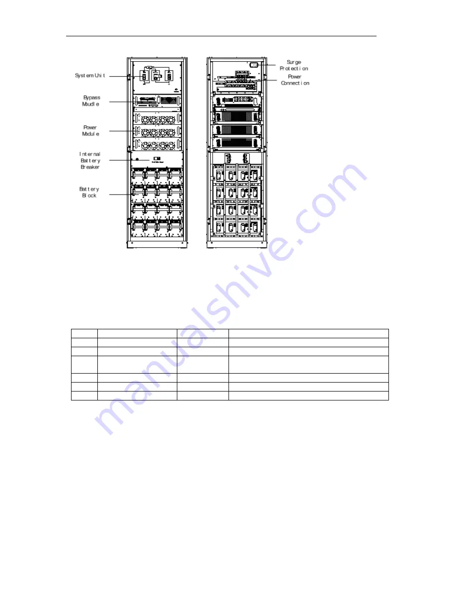
3 module cabinet including battery packs inside
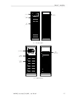
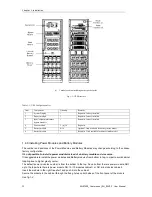
Fig.1- 1: UPS Structure
Table.1- 1: UPS Configuration List
Item
Component
Quantity
Remarks
1
System Display
1
Requisite, factory installed
2
Bypass module
1
Requisite, factory installed
3
Input/output/maintenance
bypass breakers
1
Requisite, factory installed
4
Power module
1 ≤n ≤10
Requisite
5
Battery module
0~16
Optional. Only available for battery inside model
6
Battery breaker
1
Requisite. Only available for battery inside model
1.4.8 Installing Power Modules and Battery Modules
The number and positions of the Power Modules and Battery Modules may change according to the chosen
factory configuration.
I
t’s not possible to install a power module
instead of a battery module and vice versa.
It is suggestable to install the power modules and Battery modules from bottom to top, in order to avoid cabinet
toppling due to higher gravity center.
The default power modules number is from the bottom to the top. So on bottom there is power module NO.1
up to the top where there is power module NO.10 (10 modules cabinet), or NO.6 (6 modules cabinet).
Insert the module in the right free shelf, and push it into the cabinet.
Secure the module to the cabinet through the fixing holes on both sides of the front panel of the module.
See fig.1-2


