Chapter 1 Installation
22
MUST400_User manual_EN_REV02 User Manual
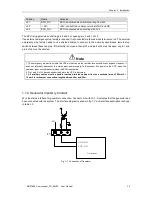
Table.1- 8: Integrated warning dry contact interface description
Position
Name
Purpose
J9.1
ALARM_NC
Integrated warning relay (normally closed) will be open during
warning
J9.2
ALARM_NO
Integrated warning relay (normally open) will be closed during
warning
J9.3
GND
Common connection
Note
All auxiliary cables must be double insulated twisted cables with cross sectional area of 0.5mm2 ~ 1.5mm2 for
maximum connection length between 25m and 50m.
1.7.8 Mains Failure Warning Output Dry Contact Interface
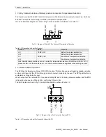
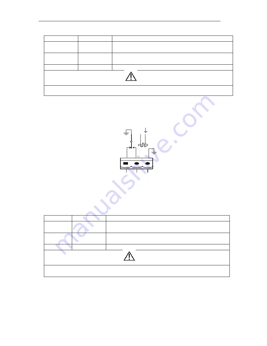
J10 is the output dry contact interface for utility failure warning, when the utility fails, the system will send a
utility failure warning information, and provide an auxiliary dry contact signal via the isolation of a relay. The
interface diagram is shown in fig.1-11, and description is shown in table.1-9.
J10
U
T
I_
F
A
IL
_N
C
U
T
I_
F
A
IL
_N
O
G
N
D
Fig.1- 11: Utility Failure Warning Dry Contact
Table.1- 9: Description of Mains failure warning dry contact
Position
Name
Purpose
J10.1
UTI_FAIL_NC
Mains failure warning relay(normally closed) will be open during
warning
J10.2
UTI_FAIL_NO
Mains failure warning relay (normally open) will be closed during
warning
J10.3
GND
Common connection
Note
All auxiliary cables must be double insulated twisted cables with cross sectional area of 0.5mm2 ~
1.5mm2 for maximum connection length between 25m and 50m.
警告
危 险
警告
危 险

