background image

2

Placement of the WAND:

The WAND comes with 50, 100 or 150 feet of
cable. A typical installation will require about 5 feet
of wire to come from the ground up and into the
control box for connection to the power supply and
control board. Check your specific installation for
exact dimensions.

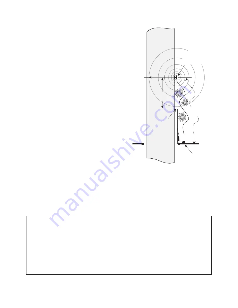
From the point on the ground where you will run
the WAND cable into the control box, lay the wire
out on a path as far as you can from the control box.
The WAND should be no more than two (2) feet
from the edge of the driveway and no closer than 25
feet from the end of the open gate.

The WAND’s RANGE can be adjusted to a maxi-
mum of 12 feet*. The movement of a gate in its
open position could cause a DISTURBANCE in the
MAGNETIC FIELD of the WAND if it comes
within the RANGE of the WAND. Make sure the
end of the open gate is a minimum of 25 feet from
the WAND. If you have a situation where the
WAND has to be buried closer than 25 feet you will
have to adjust the RANGE of the WAND to com-
pensate for the closeness.

For Optimum Performance:

• Locate the WAND as far as possible away from power transformers, power lines, under ground gas

line, and telephone lines.

• Locate the WAND away from general moving traffic to prevent unwanted activation. Remember

that the WAND detects MAGNETIC DISTURBANCES caused by a vehicle’s mass and velocity.

• It is recommended that you run the WAND cable inside PVC conduit.
• Do not run WAND cable in conduit with other wires such as power or other control wires.
• The WAND cable 

CAN NOT

 be spliced. If you need more wire, contact the GTO Sales Department

at 1-800-543-GATE (4283).

Installation Overview

:

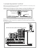
Once the best location for the WAND is determined, you are ready to bury the WAND and run the cable
underground to the control box. Connect the WAND wires and the RANGE ADJUSTMENT CONTROL
BOARD to the gate operator control board and power supply. Adjust the RANGE if necessary. Finally, place
the WARNING signs on the gate. That’s it!

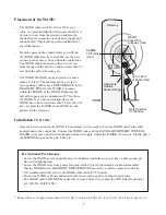
Gate Operator
Control Box

Driveway

RANGE:
12 ft. radius 
(max)

up to 145 ft. 
of Cable (max)

WAND:
2 feet from
driveway (max)

Open Gate 
Outside
Sensor Range

25 ft. from 
gate (min)

Range distance is approximate and will vary due to outside interference, type of soil, vehicle mass, speed, etc.

Summary of Contents for EXIT WAND

Page 1: ...ered gate operator we recommend you consult a certified electrician WARNING EXIT WAND INSTALLATION MANUAL WARNING WARNING WAND with 50 100 or 150 feet of Direct Burial Cable Range Adjustment Board War...

Page 2: ...te of the art manufacturing facility is located in Tallahassee Florida One of our highest priorities is to provide outstanding technical service to our customers Therefore if you have any questions or...

Page 3: ...DOUBLE SPADE CONNECTOR a wire connector which allows the connection of two wires to be con nected to a single terminal see Parts Identification on cover How the EXIT WAND works When a metal object su...

Page 4: ...or Optimum Performance Locate the WAND as far as possible away from power transformers power lines under ground gas line and telephone lines Locate the WAND away from general moving traffic to prevent...

Page 5: ...from being accidently pulled out Step 2 If you are installing the WAND on a GTO PRO low voltage single gate operator use a screwdriver or steel punch to carefully remove the thin plastic knockout disk...

Page 6: ...For installation on other brands of operators see page 10 NOTE The SHIELD is the braided metal wire wrapped around the insulated wires inside the WAND CABLE PVC Conduit WIRE CLAMP in Knockout Bottom...

Page 7: ...wer supply connection Step 12 With Power Off connect the RED and BLACK control board wires from the operator to the DOUBLE SPADE CONNECTORS provided as shown Step 13 Using a WIRE NUT connect the SHIEL...

Page 8: ...ING SENSOR IN USE The Automatic Gate Opener is activated when a vehicle comes within range of the sensor buried along side the driveway and could possibly be activated by a child on a bicycle tricycle...

Page 9: ...low fuse CLOSE OPEN FIRE DEPT SHAD LOOP SAFE LOOP ENTRY LOOP FREE EXIT CYCLE COMMON COMMON COMMON COMMON LOCK 1 LOCK 2 AUX 2 AUX 1 ACCES PWR Class 2 24VDC REV FWD GTO Inc Tallahassee FL copyright 1999...

Page 10: ...the control board make contact with other ex posed wiring or components Potentiometer POT Range Adjustment Control Board Wire Nut Optional Mounting Hole YELLOW wire from WAND YELLOW BLACK To NEGATIVE...

Page 11: ...rol board Step 13a Connect the SHIELD from the WAND CABLE to the NEGATIVE terminal of the 24 VDC Acces sory Power Terminal Block on the control board Adjusting the Range Step 15a Test the WAND to see...

Page 12: ...nnection o Connect the BLUE from the WAND to the FREE EXIT ENTRY of the gate operator o Connect the BLACK from the WAND to the COMMON GND of the gate operator Range POT board connection o Connect the...

Page 13: ...F 69 C Dimensions 1 3 4 44 5 mm diameter x 16 5 42 cm long Adjustable range 3 12 feet typical installation Very low power consumption ideal for battery application Trouble Shooting Make sure all conn...

Page 14: ...ypad can be easily installed as a wireless or wired keypad It can be programmed to use up to fifteen different personal identification number PIN codes Each code is face programmable with additional s...

Page 15: ...rned freight prepaid to GTO Inc 3121 Hartsfield Road Tallahassee Florida USA 32303 IMPORTANT Call 850 575 4144 or Fax 850 575 8950 for a Return Goods Authorization RGA number before returning accessor...

Reviews: