4
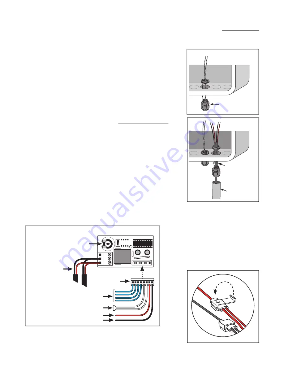
Figure 14
Low Voltage
Wire from
Lights
PVC Conduit
Installing the Photocell and Control Board
Installing the photocell and low voltage wire strain relief:
1. Use a screwdriver to remove a “knockout” in the bottom of the gate
operator control box or a weatherproof junction box. If knockouts
are not available, carefully drill a 5/8” hole, then install the photocell
as shown in
Figure 13
.
2. In another knockout or 5/8” hole, install the strain relief provided.
Run the low voltage wire from the lights through the strain relief
into the box. Secure by tightening the strain relief nut until the wire
is snug. Always run wire from the ground to the box in PVC conduit
to protect it from grazing animals and weed eaters. See
Figure 14
.
Figure 13
Photocell
Wiring the Light Kit
Installing the Photocell:
Place the Light Kit control board in the gate operator control box or a
weatherproof junction box. Connect the Light Kit control board using
Figure 15
and the Wiring Diagrams on the following pages.
1. Plug the Light Kit’s Wiring Plug to the Lgiht Kit control board. See
Figure 15
.
2. Connect the two RED wires from the lights to one of the Light Kit
control board terminals. Connect the two BLACK wires from the
lights to another Light Kit control board terminal.
IMPORTANT: Only use the two terminals shown in
Figure 15
to con-
nect the wires from the lights.
NOTE:
Included in the light kit
are four wire splicing locks. They
are used to connect the end of one
wire to the middle of another.
With wires in place, fold locking
tab over and press until it locks
in place. Make sure the locks are
clamped securly to the wires. Use
pliers if neccessary. See
Figure 16
.
Figure 16
x2
DEL
AY
TIME
R
0
60
Light Kit Control Board
Low Voltage
Wires from
Lights
RED Wire
BLACK Wire
WHITE Wires
BLUE Wires
Potentiometer for Adjusting
the Light Duration Delay
AY
TIME
AYAY
0
6
AY
TIME
AYAY
Wiring PLUG
Figure 15


