background image

7

IMPORTANT SAFETY INSTRUCTIONS

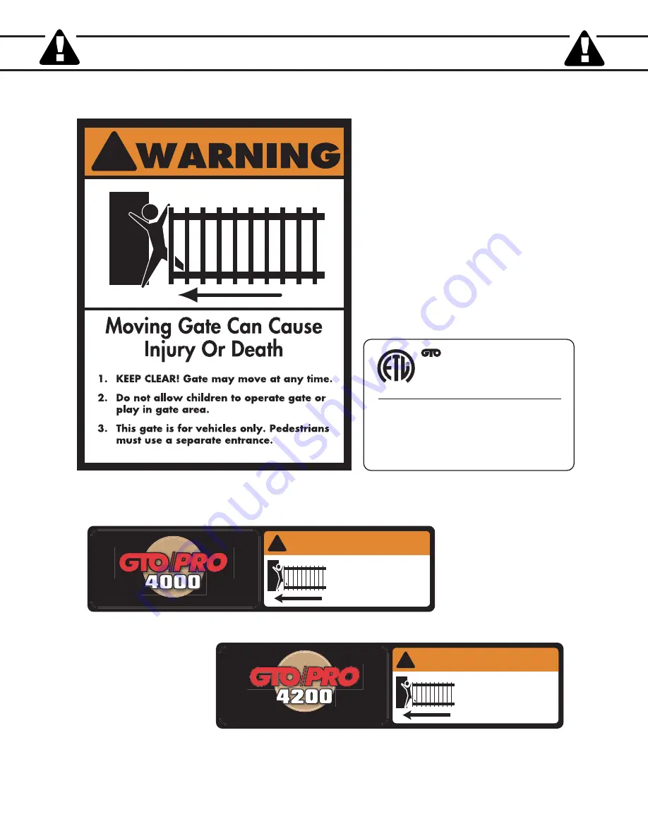
These warning labels should be found

at the locations specified below.

If any of them are missing,

immediately contact GTO for

replacements.

!

Warning signs (4 enclosed) to be installed on each side
of the gate (3–5 feet above the bottom of the gate).

Maximum Gate: 1000 lb. (453.5 kg); 20 ft. (6.1 m)
Voltage: 12 Vdc; Frequency: 0 Hz; Power: 60 W
Class I, II, III and IV Vehicular Swing Gate Operator.
Serial Number: XXXXXXXXXX

#xxxxxxx

Conforms to UL 325 STANDARDS

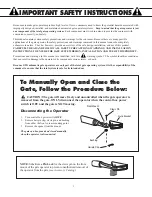
TO MANUALLY OPEN AND CLOSE THE GATE:

1. Turn control box power switch OFF.
2. Disconnect front or rear mount from gate bracket.
3. Pull operator away from front or real mounts. 

DC SW-4000 SERIES

GTO, Inc. 

Tallahassee, Florida USA

Disconnect operator ONLY when the control box power 
switch is OFF and the gate is NOT moving.

L I S T E D

US

C

Product identification and manual operation instruction 
label (1) installed on control box.

Logo and warning labels (2) installed on each side of master operator housing.

1.  KEEP CLEAR! Gate may move at any time.
2.  Do not allow children to operate gate or play in 
 

gate area.

3.  This gate is for vehicles only. Pedestrians must 
 

use separate entrance.

WARNING

!

MOVING GATE

Can Cause Injury or Death

®

DC-SERIES

1-800-543-GATE (4283) • www.gtopro.com

Logo and warning labels (2) installed on each side of slave operator housing.

1.  KEEP CLEAR! Gate may move at any time.
2.  Do not allow children to operate gate or play in 
 

gate area.

3.  This gate is for vehicles only. Pedestrians must 
 

use separate entrance.

WARNING

!

MOVING GATE

Can Cause Injury or Death

1-800-543-GATE (4283) • www.gtopro.com

®

DC-SERIES

Summary of Contents for /PRO SW-4000

Page 1: ...eleasing GTO Inc from any and all liability If you are not in agreement with this disclaimer or do not feel capable of properly following all installation and safety instructions you may return this p...

Page 2: ...access locations not servicing the general public in which unauthorized access is prevented via supervision by security personnel The GTO PRO 4000 Series Gate Operators are intended for use with vehi...

Page 3: ...Bracket page 16 Mounting the Operator page 17 Installation of the Closed Position Stop page 18 Mounting the Control Box page 19 Connecting the Operator Power Cable page 20 Installing the Battery page...

Page 4: ...other access control products These optional accessories see the Accessory Catalog are available The GTO PRO 4000 4200 Operators feature adjustable obstruction sensing This safety feature makes the ga...

Page 5: ...ns and warnings in this manual are identified with this warning symbol The symbol identifies conditions that can result in damage to the operator or its components serious injury or death Because GTO...

Page 6: ...d size of gate its frequency of use and the proper class rating 2 Make sure the gate has been properly installed and swings freely in both directions Repair or replace all worn or damaged gate hardwar...

Page 7: ...d 3 Devices such as contact sensors safety edges and non contact sensors photo beams provide additional protection against entrapment 4 If push buttons or key switches are installed they should be wit...

Page 8: ...ay to it at least once per month 7 Service the gate and gate operator regularly Grease hinges spray push pull tube with high quality silicon spray and replace the battery every 3 5 years 8 To operate...

Page 9: ...Type A an inherent i e built in entrapment sensing system as the primary type of entrapment protection Also the GTO PRO 4000 4200 has provisions for the connection of Type B2 protection to be used as...

Page 10: ...operation and are required when installing the GTO PRO 4000 4200 Automatic Gate Operators Furthermore a walk through gate must be installed if pedestrian traffic is expected near the vehicular gate W...

Page 11: ...ida USA Disconnect operator ONLY when the control box power switch is OFF and the gate is NOT moving L I S T E D US C Product identification and manual operation instruction label 1 installed on contr...

Page 12: ...3 3 8 x 3 16 Bushing 2 3 8 x 3 4 Bushing 2 1 2 Lock Nut 4 3 18 Lock Nut 2 Hardware Gate Bracket 1 Post Pivot Bracket 1 Customer Support Card Post Bracket 1 Closed Position Stop Plate 1 2 Receiver Moun...

Page 13: ...power cable Hairpin Clip 2 3 8 x 3 1 2 Clevis Pin 1 1 2 x 2 3 4 Bolt 2 3 8 x 3 3 4 Bolt 2 1 2 x 10 Carriage Bolt 2 8 Nylon Cable Tie 10 1 2 Washer 4 3 8 Washer 3 3 8 x 3 16 Bushing 2 3 8 x 3 4 Bushin...

Page 14: ...x See page 22 Powering the System and the Accessory Catalog for wire and solar charging panels If the gate is more than 1000 away from an AC power source you will need to use at least one GTO Solar Pa...

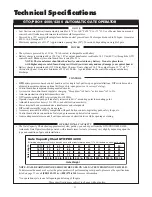
Page 15: ...ode GTO remote mounted RF receiver tuned to 318 MHz Operator length with push pull tube fully retracted is 461 4 mounting point to mounting point Adjustable auto close timer 15 to 120 s and obstructio...

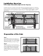
Page 16: ...e of a pull to open installation on a chain link fence and single gate Mounting the operators on a masonry columns require special procedures see Column Installation Information on page 38 if you inte...

Page 17: ...han those supplied On wood posts use a metal plate not provided between the nuts and post to prevent the operator from pulling the bolts and washers through the wood On masonry columns use red heads o...

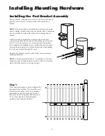
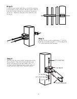
Page 18: ...holes in fence post as marked using a 1 2 drill bit Install the post bracket using the 1 2 x 10 carriage bolts 1 2 washers and lock nuts provided Step 2 Position the post bracket on the fence post wi...

Page 19: ...ear mount bushing and post pivot brackets and secure with the clevis pin and hair pin clip Step 6 Place a small bushing under the the front mount and attach the gate bracket to the front mount using t...

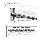
Page 20: ...n t have 2 inches of clearance or the gate operator is binding on the post pivot bracket remove the bolt in the post bracket and readjust the pivot bracket until you can achieve the proper clearance W...

Page 21: ...e post bracket assembly if necessary Level Operator Fence Post Clevis Pin Bushing and Hairpin Clip Mounting the Operator You will need to install the GTO PRO 4200 SLAVE operator arm on the second gate...

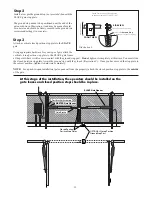
Page 22: ...from the control box will be referred to as the SLAVE gate and gate operator Illustration A Closed Position Stop Plate mounted horizontally on metal post with U bolts SLAVE Gate Frame MASTER Gate Fram...

Page 23: ...y NOTE For a push to open installation gate opens out from the property attach the closed position stop plate to the outside of the gate Step 2 Install a low profile ground stop not provided beneath t...

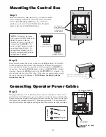
Page 24: ...t Hub Lock Nut Strain Relief NOTE The battery that came with your GTO PRO 4000 4200 MUST be placed in the top horizontal battery slot with the terminals on the RIGHT The extra vertical battery slot is...

Page 25: ...t the stripped wires of the power cable into the appropriate terminals on the SLAVE OPERATOR terminal block The green wire should be inserted into the GRN terminal the blue wire into BLU the orange wi...

Page 26: ...sure the distance from this outlet to the control box following the path where the wire will be laid After you have measured how much wire is needed cut the wire to the appropriate length Not more tha...

Page 27: ...5 Strip 3 16 off the ends of the low voltage wire and twist tightly Attach these ends to the 18VAC terminals located on the POWER IN terminal block see illustration at right Be certain not to let the...

Page 28: ...strongly recommended Step 6 Strip 1 2 of insulation from the ends of the low voltage wire Attach these stripped ends to the transformer terminals A dab of household petroleum jelly on each terminal w...

Page 29: ...e Switching this to OFF only disables the open and close warning not the obstruction warning DIP Switch 3 Auto Close With the Auto Close switch in the OFF position the gate will remain open until it r...

Page 30: ...en simultaneously SLAVE gate starts to close 8 seconds before MASTER gate 1 ON 2 3 4 DUAL MODES ON OFF 1 2 3 4 1 ON 2 3 4 DUAL MODES ON OFF 1 2 3 4 1 OFF 2 OFF 1 ON 2 OFF and 3 OFF 1 ON 2 OFF and 3 ON...

Page 31: ...conds Step 4 Press the transmitter button and allow the gates to return to the fully open position YOUR FIRST GATE S CLOSED POSITION LIMIT IS NOW PROGRAMMED Step 5 Activate your operators again by pre...

Page 32: ...sition BOTH YOUR MASTER AND SLAVE GATE S CLOSED POSITION LIMITS ARE NOW PROGRAMMED TESTING YOUR CLOSED LIMIT SETTING Press your entry transmitter and allow your gates to close If CLOSED positions are...

Page 33: ...this equipment Such modifications could void the user s authority to operate the equipment Obstruction Sensitivity Potentiometer ALWAYS KEEP SAFETYAT THE TOP OF YOUR LIST WHEN ADJUSTING OR SERVICING...

Page 34: ...fety device wiring to the terminal blocks Unplugging the transformer does not turn power to the operator OFF Contact Sensor Input Connection Connect one of the OPEN EDGE contact sensor wires to the CO...

Page 35: ...PLEASE NOTE Non contact sensors are not included with the GTO PRO 4000 Wire from Non Contact Sensor photo beam STALL FORCE M I N M A X GRN BLK RED RECEIVER COM COM CYCLE CLOSE SAFETY EXIT OPEN SHADOW...

Page 36: ...to the COMMON COM terminal and the other to the CYCLE CLOSE terminal on the GTO PRO 4000 control board Each activation of the accessory will cause the gate to cycle as follows OPEN STOP CLOSE STOP If...

Page 37: ...position for the post pivot bracket insert the 5 16 x 1 3 4 bolt through the aligned holes of the post bracket and post pivot bracket and fasten it with the 5 16 washer and nut IMPORTANT If you loosen...

Page 38: ...er switch ON The control board is now configured to push the gate open Setting the Open Position Limit Step 1 Confirm that the power switch is in the ON position and the gate is in the CLOSED POSITION...

Page 39: ...will need to CLEAR your OPEN LIMIT settings and follow steps one 1 to four 4 again CLEARING PROGRAMMED OPEN LIMIT SETTING If you make a mistake and set the limit at the wrong position press your tran...

Page 40: ...or broken or spliced wires Check the Red STATUS LED on the Control Board IF THE LED IS ON but the unit is not working 1 Check the battery in your transmitter and replace with a fresh one if needed 2 V...

Page 41: ...easure voltage at panel and control box 12 V Battery ________________________________12 0 to 13 5 Vdc 7 0 Ah Charging circuit _____________________________12 0 to 14 8 Vdc measure voltage with battery...

Page 42: ...rization RGA number to you 4 Securely pack the component s authorized for return to the factory Write the RGA number issued to you on the outside of the package in LARGE BOLD PRINT Ship the package s...

Page 43: ...t toward the column It is recommended that you place a steel plate between the operator mounting brackets and masonry surface for additional strength B If a push to open installation is impossible due...

Page 44: ...er is a miniature version of the GTO PRO 4000 4200 entry transmitter and has the same adjustable code settings 12 Volt battery included Entry Transmitter RB741 The GTO PRO entry transmitter with adjus...

Page 45: ...Door Receiver 9 Volt battery included Replacement Battery RB500 Standard 12 volt 7 0 amp hour maintenance free battery for the GTO PRO 2000 GTO PRO 3000 3200 GTO PRO 4000 4200 gate operator systems Th...

Reviews: