18
Terminals
(Note: use common connections for ground.)
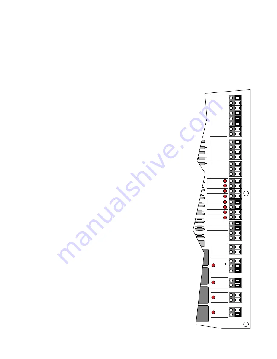
EDGE 1 – EDGE 6: These six terminals accommodate safety edges and
photo beams.
DUAL GATE INTERFACE RX TX: allows the addition of a second gate
operator for dual gate systems (see Installing a Dual System on pages 22-23).
GTO RCVR: Terminal block reserved for a GTO receiver ONLY. Other
receivers may be connected to the 24 VDC terminal block (see CAUTION
at 24VDC below).
OPEN/CLOSE: OPEN requires constant pressure on entry device to open
the gate; CLOSE requires constant pressure on entry device to close the gate.
NOTE: When a constant pressure entry device is installed the unit will not
accept any other open or close input except FIRE DEPT and FREE EXIT
(requires constant input).
FIRE DEPT.: N/O contact reserved for public safety agency use
(e.g., fire box) only.
SHAD. LOOP: Shadow loop setting.
SAFE LOOP: N/O contact that prevents the gate from closing if the safety
device (ground loop, photo beam, etc.) is activated.
ENTRY LOOP: N/O contact for entry device.
FREE EXIT: N/O contact for an exit loop or exit wand.
CYCLE: N/O contact for doorbell button or key switch.
24 VDC: Accommodates accessory power up to 1/2 A. This is a fused power
supply (1/2 A; 3AG fuse only). CAUTION: Accessories other than 24 Vdc
or rated higher than 1/2 A require a separate power supply (not provided).
AUX2: Activates devices such as another unit in a 2-stage security application.
ALARM: Activates devices such as lights or alarms when gate is obstructed.
LOCK2: Provides a contact closure when the gate is in motion.
LOCK1: Provides a contact closure when the gate is not in motion.
EDGE 6
EDGE 5
EDGE 4
EDGE 3
EDGE 2
EDGE 1
COM
COM
+
–
DUAL
GATE
INTER-
FACE
RX
TX
G
R
B
GTO
RCVR.
CLOSE
OPEN
FIRE DEPT.
SHAD. LOOP
SAFE LOOP
ENTRY LOOP
FREE EXIT
CYCLE
COMMON
COMMON
COMMON
COMMON
LOCK 1
LOCK 2
ALARM
AUX 2
ACCES. PWR
24VDC
–
+
–
+
TB11
TB9
TB10
TB8
TB7
TB6
TB5
TB4
TB3
TB2
TB1
Terminals
Error Condition LEDs
(Press RST / LEARN to clear these LEDs)
SENSOR ERR.: Indicates obstruction sensing circuitry has malfunctioned.
LIM SW ERR.: Indicates a fault in the limit switch or limit switch wiring. This LED cannot be reset using the RST/
LEARN button.
OPEN MTR.: Control board does not detect the operator motor.
INTERN ERR.: Indicates a microprocessor error has occurred. An internal error cannot be reset by pressing the RST/
LEARN button. The power must be turned OFF, then back ON to reset this LED.
Proceed to SETTING A PERSONAL TRANSMITTER CODE on the next page.


