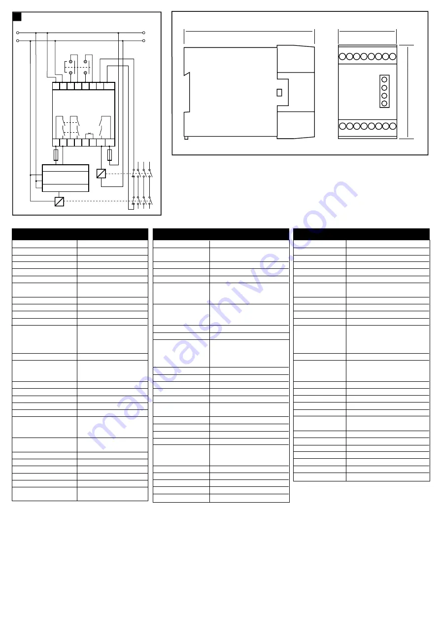
120
45.5
73
Technical Specifications
Conforming to standards:
EN60204, EN954-1
Power supply:
24V AC/DC
Power consumption:
<4VA
X1-X2 contactor monitoring loop: N/C contactor loop
Safety inputs:
2 x N/C switches
Internal fuse:
500mAT Replaceable supply fuse
Relay outputs:
2N/O and 1N/C. TUV approved
1N/O delay output TUV approved
Utilisation cat. (AC):
4A / 250VAC / 1000VA at COSØ=1
Max. switched DC current/voltage: 2A / 30VDC / 60W
Min. switched current/voltage:
10mA / 10V
Max. output fuse:
5A quick acting
Indication
LED 1
Red
= Power ON
LED 2
Green
= K1 Closed
LED 3
Green
= K2 Closed
LED 4
Green
= Delay Output Closed
Impulse withstand voltage:
2500V
Max. drop out time:
50mSec Instant
Part No: 23048
0.1 Sec to 10 Sec Delay Output
Part No: 23057
1 Sec to 35 Sec Delay Output
Operating temperature:
-10
°
C to +55
°
C
Contamination level:
III
Humidity:
90% RH at +50
°
C
Degree of enclosure protection:
IP40 DIN 0470
Terminal isolation:
IP20 DIN 0470
Max. conductor size:
1 x 2.5mm
2
stranded wire with sleeve
stripped
8mm,
1 x 4mm
2
solid conductor
Terminals: Plus-minus
screws
M3.5
Box terminal with wire protection
Weight: 415g
Material and colour:
Red polycarbonate
Housing:
16 way D=120 H=73 W=45.5
Installation group:
C in accordance with VDE 0110
Fixing details:
35mm DIN rail
Miscellaneous:
Delay time is set by internal variable
resistor
Technische Date
Entspricht den Normen:
EN 60204/DIN VDE 0113, EN 954-1
Gehäuse: Schnellbefestigung
auf
Normschiene,
16 Klemmen, 73 x 45,5 x 120 mm
Gehäusematerial: Polycarbonat,
rot
Montage:
35 mm DIN-Hutschiene
Schutzklasse: Entfällt (Einbaugerät nach E-DIN 50178)
Anschlüsse:
Schraubanschlüsse für 2 x 1,5 mm
2
Litze mit
Hülse; max. Länge der abisolierten
Anschlußleitungen 8 mm; 1 x 4 mm
2
massiv
Leiterbefestigung:
Plus-Minus-Klemmenschrauben M3,5;
Kastenklemme mit selbstabhebendem
Drahtschutz
Schutzart: Anschlüsse IP 20, Gehäuse IP 40
Feuchtigkeit:
Max. 90 % bei +55
°
C
LED-Anzeigen:
1: Rot = Betriebsspannung (Power)
2:
Grün = Ausgang K1
3:
Grün = Ausgang K2
4:
Grün = verzögerter Ausgang
Betriebsspannung: 24
VAC/DC
Leistungsverbrauch:
< 4 VA
Interne Sicherung:
500 mAT (austauschbar)
Eingang: 2
Öffnerkontakte (S13/S14, S23/S24)
X1/X2: Schütz-Hilfskontakt
Freigabeausgänge: 2
Schließer (13/14, 23/24) unverzögert
1
Schließer (47/48) verzögert
Zusatzausgang: 1
Öffner (31/32); nur für Meldezwecke
Gebrauchskategorie Ausgänge: AC-15: 3 A/250 VAC; DC-13: 3 A/24 VDC
Minimaler Strom/Spannung:
10 mA/10 V
Max. Absicherung der Ausgänge: 5 A fl.
Abfallzeit:
Typ. 50 ms (unverzögert)
Bestell Nr: 23048
0,1 - 10 s (verzögert)
Bestell Nr: 23057
1 - 25 s (verzögert)
Überspannungskategorie:
II nach DIN VDE 0110
Verschmutzungsgrad:
3 nach DIN VDE 0110
Betriebstemperatur: -10
°
C bis +55
°
C
Gewicht: 415
g
Einstellung: Verzögerungszeit wird an internem
Specifications techniques
Conforme aux normes :
EN954-1, EN60204
Alimentation :
24 VDC / VAC
Consommation :
< 4VA
Bornes X1-X2 :
Boucle de retour pour contrôle et réarmement
Entrées de sécurité :
2 contacts N/C
Fusible interne :
500mA remplaçable
Contacts de sortie :
2 N/O + 1 N/C instantanés approuvés TUV
1 N/O temporisé approuvés TUV
Pouvoir de coupure max : 4A/250VAC/1000VA à COSO=1
Charge/courant/tension : 2A/30VDC/60W
Pouvoir de coupure min :
10 mA/10V
Fusible de sortie externe : Max 5A à fusion rapide
Lampes :
LED1 Rouge : Alimentation ON
LED2 Verte 1 :K1 fermé
LED3 Verte 2 :K2 fermé
LED4 Sortie temporisée fermée
Tension d’isolement :
2500V
Temps de réponse :
50mS pour les sorties instantanées
Ref: 23048
0.1S à 10 S pour la sortie temporisée
Ref: 23057
1 S à 35 S pour la sortie temporisée
Température ambiante :
-10
°
C à + 55
°
C
Niveau de contamination : III
Humidité :
90% de RH à + 50
°
C
IP Boîtier :
IP 40 DIN 0470
IP Bornier :
IP 20 DIN 0470
Choix des câbles :
1 X 25 mm
2
souple avec cosses 8mm,
1X 4 mm
2
rigide
Bornes :
Vis M3.5 Plus/Moins avec protection câble
Poids :
415 grs
Matériaux et couleur :
Polycarbonate rouge
Boîtier :
16 voies P=120 mm, H=73mm, L=45.5mm
Groupe d’installation :
C en accord VDE 0110
Fixation :
Rail Din 35 mm
Réglage temporisation:
Par potentiomètre en face avant sous capot
4
(n)
Wiring Examples
SUPPLY
Interlock Switch or E-STOP
K1
K2
SUPPLY
A1 A2 S13 S14 S23 S24 X1 X2
K1
K2
13 14 23 24
SUPPLY CH1
CH2
MSR15D
47 48
31 32
K2
K1
IMMEDIATE
DELAYED
AUX
OUTPUTS
INPUTS
PLC
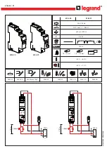
Summary of Contents for Minotaur MSR15D
Page 4: ...DrgNo 23898 IssueNo 2 R ...


