background image

Ø

: Total Working Angle

X

: Working Distance

Along Leading Edge

Y

: Distance From

Leading Edge

X

Y

ø

X

Leading Edge


G

ua

rd

ia

Fa

ll 

Pr

ot

ec

tio

  6

30

S.

 2

31

st

 S

t.

, K

en

t,

 W

A

 9

80

32


 p

ho

ne

: (

80

0)

 4

66

-6

38

 f

ax

: (

80

0)

 6

70

-7

89


  w

w

w

.g

ua

rd

ia

nf

al

l.c

om

3

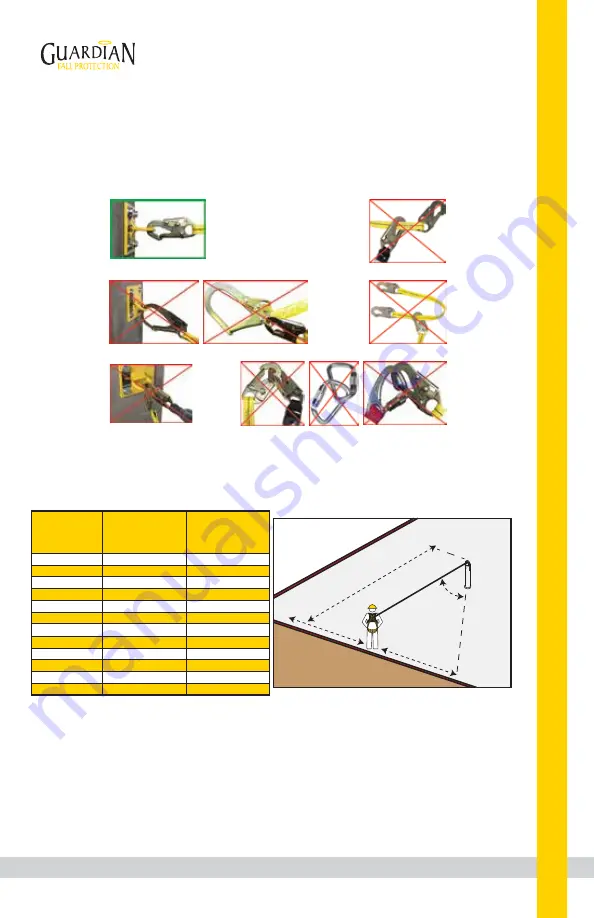
Compatibility:

 When making connections with Metal Energy Absorber, eliminate all possibility of roll-out. 

Roll-out occurs when interference between a hook and the attachment point causes the hook gate to 
unintentionally open and release. All connections must be selected and deemed compatible with Metal 
Energy Absorber by a Competent Person. All connector gates must be self-closing and self-locking, and 
withstand minimum loads of 3,600 lbs. See the following for examples of compatible/incompatible 
connections:

Correct Anchorage Positioning:

This chart details allowable working zones required

to reduce risk of swing falls and improper side loading.

ALWAYS adhere to information specified by chart.

Anchor Distance

From

Leading Edge (Y)

Working Distance

Along Roof Edge

(Either Direction) (X)

Working Angle

From

Perpendicular (Ø)

6’

10’
15’
20’
25’
30’
35’
40’
45’
50’
55’
60’

8’

9’ - 9”

11’ - 7”
13’ - 3”
14’ - 6”

16’

17’ - 2”
18’ - 3”
19’ - 4”

19’ - 10”

21’ - 4”
22’ - 3”

53°
45°
38°
33°
30°
28°
26°
24°
23°
21°
21°
21°

For example, if the anchorage connector is 6’ from the leading

edge (Y), the working distance (X) is 8’ in each direction from

the perpendicular, which translates to a 53° working angle.

Swing Falls:

 Prior to installation or use, make considerations for eliminating or minimizing all swing fall

hazards. Swing falls occur when the anchor is not directly above the location where a fall occurs. Always work
as close to in line with the anchor point as possible. Swing falls significantly increase the likelihood of serious
injury or death in the event of a fall.

As shown in following image, there are potential danger zones for swing falls when using a single HLL span.
Use multiple HLL spans to expand area of coverage.

Connector
closed and
locked to
D-ring. 

OK.

Connector
to integral
lanyard.

NO.

Two or
more snap
hooks or
carabiners
connected
to each
other. 

NO.

Two connectors
to same
D-ring. 

NO.

Connector
directly to
webbing.

NO.


Incompatible
or irregular
application,
which may
increase risk
of roll-out. 

NO.

Summary of Contents for 15206

Page 1: ...tions Read and understand these instructions before using equipment Introduction 1 Applicable Safety Standards 1 Worker Classifications 1 Safety Information 10 11 Product Specific Applications 2 Limitations 2 4 Components and Specifications 5 6 Maintenance Cleaning and Storage 9 Inspection 9 Installation and Use 6 9 Inspection Log 10 Labels 11 ...

Page 2: ...ssociated components Worker Classifications CAUTION Understand the following definitions of those who work near or who may be exposed to fall hazards Qualified Person A person with an accredited degree or certification and with extensive experience or sufficient professional standing who is considered proficient in planning and reviewing the conformity of fall protection and rescue systems Compete...

Page 3: ...tical horizontal Applicable D rings Dorsal Chest Side Shoulder WARNING Use of equipment in unintended applications may result in serious injury or death Maximum 1 attachment per connection point For all applications worker weight capacity range including all clothing tools and equipment is 130 420 lbs Limitations Fall Clearance There must be sufficient clearance below the anchorage connector to ar...

Page 4: ...ng Roof Edge Either Direction X Working Angle From Perpendicular Ø 6 10 15 20 25 30 35 40 45 50 55 60 8 9 9 11 7 13 3 14 6 16 17 2 18 3 19 4 19 10 21 4 22 3 53 45 38 33 30 28 26 24 23 21 21 21 For example if the anchorage connector is 6 from the leading edge Y the working distance X is 8 in each direction from the perpendicular which translates to a 53 working angle Swing Falls Prior to installati...

Page 5: ...6 6385 fax 800 670 7892 www guardianfall com 4 SAFE ATTACHMENT ZONE DANGER ZONE WORK IN THIS AREA NOT ALLOWED Horizontal Lifeline 100 120 60 SAFE ATTACHMENT ZONE EXTENDS FOR ENTIRE BUILDING ROOF PERIMETER Horizontal Lifeline 120 PLACE HLL 6 10 BACK FROM LEADING EDGE 60 ...

Page 6: ...ips 2 CB 1 W Anchors 2 2 5 O rings Metal Energy Absorber System for Column Ceiling Mount Applications Over 60 Includes 2 Energy Absorbers 3 Shackles 2 Thimbles 1 Turnbuckle 6 Fist Grips 2 CB 1 B Anchors 2 2 5 O rings Metal Energy Absorber System for Column Ceiling Mount Applications Over 60 Includes 2 Energy Absorber 3 Shackles 2 Thimbles 1 Turnbuckle 6 Fist Grips 2 6 Premium Cross Arm Straps 2 2 ...

Page 7: ...d by this instruction manual NEVER over tighten cable Proper sag in cable reduces forces of Fall Arrest 6 If performing installation at heights over 6 ALWAYS use a complete and independent PFAS until Metal Energy Absorber HLL System is fully installed and able to withstand forces of Fall Arrest as specified by this instruction manual Always maintain 100 tie off Guardian recommends using 3 8 diamet...

Page 8: ...n until at least 1 full thread is visible 7 Place wire rope thimble on other end of turnbuckle Tighten bolt until at least 1 full thread is visible Attach second steel shackle and thimble to anchor point or Metal Energy Absorber at opposite end of system second turnbuckle is not used Slack 6 Tightening bolts on the Absorbinator system YES NO 3 Attach Metal Energy Absorber to anchor point using pro...

Page 9: ...7 Class IPS XIP or XXIP sizes 1 and smaller For other classes of wire rope not mentioned above we recommend contacting Crosby Engineering to ensure the desired efficiency rating The style of wire rope termination used for any application is the obligation of the user 1 Refer to Table 1 in following these instructions Turn back specified amount of rope from thimble or loop Apply first clip one base...

Page 10: ... all dirt corrosives and contaminants from Metal Energy Absorber before and after each use If Metal Energy Absorber cannot be cleaned with plain water use mild soap and water then rinse and wipe dry NEVER clean Metal Energy Absorber with corrosive substances When not in use store equipment where it will not be affected by heat light excessive moisture chemicals or other degrading elements Prior to...

Page 11: ...not misuse equipment Workplace conditions including but not limited to flame corrosive chemicals electrical shock sharp objects machinery abrasive substances weather conditions and uneven surfaces must be assessed by a Competent Person before fall protection equipment is selected The analysis of the workplace must anticipate where workers will be performing their duties the routes they will take t...

Page 12: ... Equipment subjected to forces of fall arrest must immediately be removed from use Age fitness and health conditions can seriously affect the worker should a fall occur Consult a doctor if there is any reason to doubt a user s ability to withstand and safely absorb fall arrest forces or perform set up of equipment Pregnant women and minors must not use this equipment Physical harm may still occur ...

Reviews: