9
Expert Power Control 8221/8226
© 2022 GUDE Systems GmbH
Device Description
Twin Port
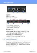
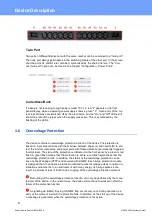
Two ports of different Banks but with the same number can be combined to a "twin port".
Then one port always participates in the switching status of the other port. In the screen-
shot the ports A1 and B1 are combined, symbolized by the chain link icon. The "Con-
nect twin port" option can be found in the chapter "Configuration - Power Ports" .
Currentless Bank
If a bank is not receiving enough power smaller 70 V), a red "L" appears in the front
panel display, while a operating power supply shows a green " L". Upon entry of the cur-
rent loss all relays are switched off by the electronics, but the "On" and "Off" LEDs still
show the state of the relays when the supply was active. This is symbolized by the
flashing of the LEDs.
1.6
Overvoltage Protection
The device contains an overvoltage protection at each of the banks. The protection is
based on input side varistors with thermal fuse between phase (L) and neutral (N) to pro-
tect the internal electronics and power ports with failure detection (permanently triggered
thermal fuse). The state of the protection is indicated on the front panel by a green or red
flash. A green flash means that the protection is active, a red flash symbolizes that the
overvoltage protection fails. In addition, the status of the overvoltage protection can be
seen on the Webpage (HTTP) and acquired with SNMP. Each surge protection module
is designed that it can derive a practical unlimited number of voltage pulses in normal in-
stallation environments. In an environment with many energy rich surge pulses it can
result in permanent loss of function due to aging of the overvoltage protection element.
Recovering of the overvoltage protection function can only be performed by the manu-
facturer of the device. In the normal case, the device will continue to work even after the
failure of the protective function.
A signaling via E-Mail, Syslog or SNMP trap occurs only once during operation, ex-
actly at the moment in which the protection fails. In addition, at the start up of the device
a message is generated, when the overvoltage protection is not active.
Summary of Contents for Expert Power Control 8221 Series
Page 2: ...2 Expert Power Control 8221 8226 2022 GUDESystems GmbH ...
Page 5: ...Device Description ...
Page 14: ...Operating ...
Page 25: ...Configuration ...
Page 54: ...Specifications ...
Page 109: ...Support ...


