8
Expert Power Control 8221/8226
© 2021 GUDE Systems GmbH
Device Description
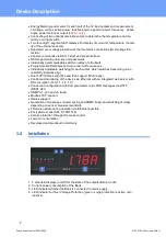
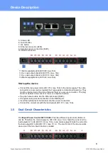
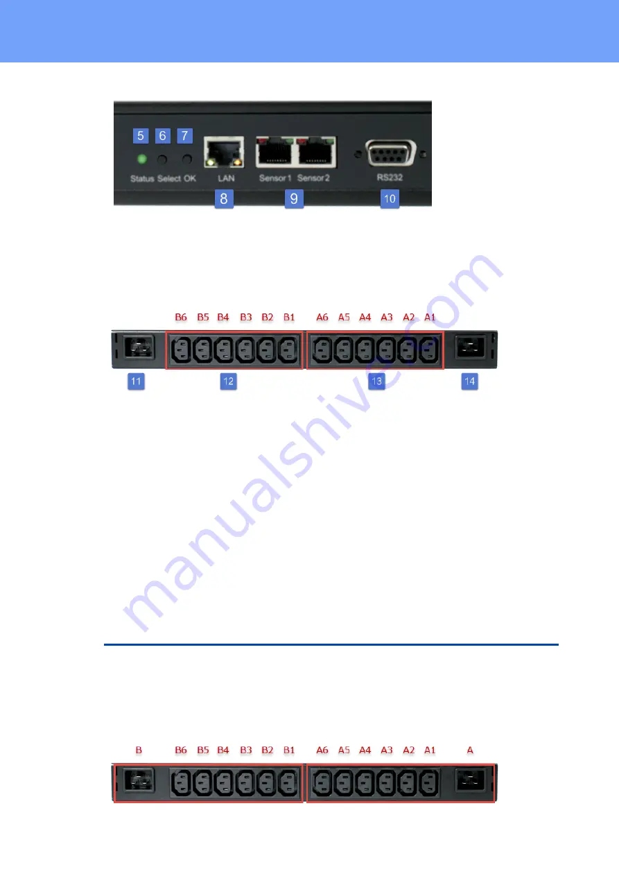
5. Status LED
6. Select button
7. Ok button
8. Ethernet connector (RJ45)
9. External sensor connectors (RJ45)
10. RS232 connector
11. Mains supply Bank B (IEC C20, max.16A)
12. 6 x Load outputs Bank B (IEC C13, max. 16A)
13. 6 x Load outputs Bank A (IEC C13, max. 16A)
14. Mains supply Bank A (IEC C20, max.16A)
Start-up the device
·
Connect the two power cords (IEC C19, max. 16A) to the mains supply. The cable
connectors are secured as regards their type against unintentional loosening. They
must be inserted up to the stop, otherwise there is no secure connection. The plug
must not wobble in the socket, or there is no tight connection.
·
Plug the network cable into the Ethernet socket (RJ45).
·
If required, setup a serial connection to the RS232 port.
·
Insert the optional external sensors into the sensor connectors.
·
Connect the consumers with the load outputs (IEC C13, max. 10A).
1.5
Dual-Circuit Characteristics
The
Expert Power Control 8221-1/8226-1
has two different input circuits (Banks A
and B). Therefore the mains supply A ( IEC C20, max. 16 A ) feeds the current to the
load outputs A1 to A6 (IEC C13, max. 10 A), resp. mains supply B feeds the current to
the load outputs B1 to B6 (IEC C13, max. 10 A ) . The electronics of the device works
when one of the two input circuits is supplied .
Summary of Contents for Expert Power Control 8221 Series
Page 2: ...2 Expert Power Control 8221 8226 2021 GUDE Systems GmbH ...
Page 5: ...Device Description ...
Page 13: ...13 Expert Power Control 8221 8226 2021 GUDE Systems GmbH Device Description ...
Page 14: ...Operating ...
Page 24: ...Configuration ...
Page 50: ...Specifications ...
Page 91: ...Support ...


