screws (pic. 30/ pos. A) and take the transmission plate
(pic. 31/ pos. B) out.
Remove the drive belt when the upper gear wheel is
turning and take it out of the engine shaft (pic. 32 – 33).
Installation in a reversed order.
Important:
To switch the machine on, the sprocket wheel
box cover (picture 14/pos.4) must be fitted.
Caution:
To change the cogged belt, switch the machine off and
disconnect it from the power source.
Changing the machine fuse (pic. 22/ pos. B)
Caution!
Switch the machine off and disconnect it
from the power source!
If the lathe is not working, check the fuse in the fuse holder
(B) and change it for a new one with the same nominal
value if necessary.
Slide backlash adjusting
If there is a too big backlash in guiding of the slide, you
can adjust it using the handrail bolts secured by a lock nut
on the side of the slide.
Caution:
Reverse backlash in the feed spindles up to one and a half
revolutions is conditioned by the design.
Carbon brushes
Have the carbon brushes checked by a professional
electrician if sparks are produced excessively.
Caution! Carbon brushes may only be changed by
a professional electrician.
Transport and storing
For machine transport, the bed slide must be moved to the
end of the bed near the tailstock where the bed slide will be
clamped.
Servicing and maintenance
System plug to be disconnected before any
servicing or maintenance!
Continuous maintenance must be provided when using the
machine. By this, high operating accuracy and reliability will
be kept for a long time of using the machine.
1.
Use a brush to remove the turnings.
2. All moving parts must be lubricated before and after
operating the machine.
3. The slide and guide surfaces must be continuously
cleaned to remove turnings and the metal abrasion,
especially when machining grey cast iron, brass, bronze,
aluminium and lubricated again. Surfaces not to be
cleaned by compressed air. Use a brush or vacuum for
cleaning.
4. Check if the metal abrasion is not present on the felt
wipers between the guide surfaces. Remove the metal
abrasion, clean the felt wipers, refit them so that they fit
tightly to the guide surfaces from all sides. Lubricate the
felt and the guide surfaces.
5. To maintain the high machine accuracy, the centres,
guide surfaces, feed spindle, etc. must be treated with
due care.
If any damage is identified when inspecting the
machine, it must be immediately removed.
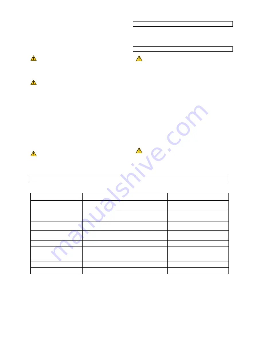
Maintenance plan (image no. 4)
APPLY ONLY LUBRICATING GREASE FREE OF RESIN AND ACIDS ON FRICTION AND ANTI-FRICTION BEARINGS!
Machine part
Frequency
Lubricating grease type
Guide spindle
After each use
Pre-clean with detergent and spray oil,
then apply the lubricant grease
Friction bearings of the guide
spindle
1x per month or after 10 hours of duty
Lubricant grease
Machine bed, dog chuck,
machine surface
After each use
Detergent and spray oil
Bearing shell and shaft of the
shifting wheels transmission
Upon each shifting wheel replacement or after 10
hours of duty
Lubricant grease
Guide screw nut
1x per month or after 10 hours of duty
Lubricant grease
Sliding spindle of the
transverse sliders with
adjustable bolt nut
1x per month or after 10
hours of duty
Lubricant grease
Sliding spindle of the bed slides
1x per month or after 10 hours of duty
Lubricant grease
Sliding spindle of the quill
1x per 3 months or after 30 hours of duty
Lubricant grease
Summary of Contents for GMD 400
Page 5: ...9 10 11 12 13 14 3 41 4 4 4 6 7 5 B 6 5 7 B B D 33 Pos 1 Pos 2 Pos 3 a a 1 ...
Page 6: ...15 16 17 18 19 c b b c c b A B C D d d I II III E ...
Page 7: ...20 21 22 23 24 25 9 10 28 27 26 B 9 10 11 13 32 43 ...
Page 8: ...26 27 28 29 30 31 A A A 23 20 A A B 20 ...
Page 9: ...32 33 ...
Page 78: ......
Page 79: ......
Page 80: ...GÜDE GmbH Co KG Birkichstrasse 6 74549 Wolpertshausen Deutschland ...


