background image

730372.doc 3429 

5


Control cable wires 

- the small wires within a gray casing that carry your commands from 

the control panel to the spot/flood light. 

CAUTION!  

DO NOT CONNECT THE  CONTROL WIRES (with connectors)  

TO ANY SUPPLY WIRES. 


DO NOT REVERSE THE RED (POSITIVE) AND BLACK (NEGATIVE) POWER WIRES. 

This spot/flood light requires a source of 12 volt DC power that is capable of supplying 10 amps of 
current even when other equipment is operating.  For best results, run two new wires from the red   
(

+

)

 positive and black (

) negative power wires of the light directly to the main 12 volt DC 

accessory panel.  Install fuse and fuse holders as shown in diagram.  A 10 amp circuit breaker can 
be installed instead of an in-line 10 amp fuse.  If the light will be less than 30 feet (9m) from its 

power source, use 12 gauge (3mm) power supply wires. If the distance will be more than 30 feet 

(9m), use 10 gauge (5mm) wires. 
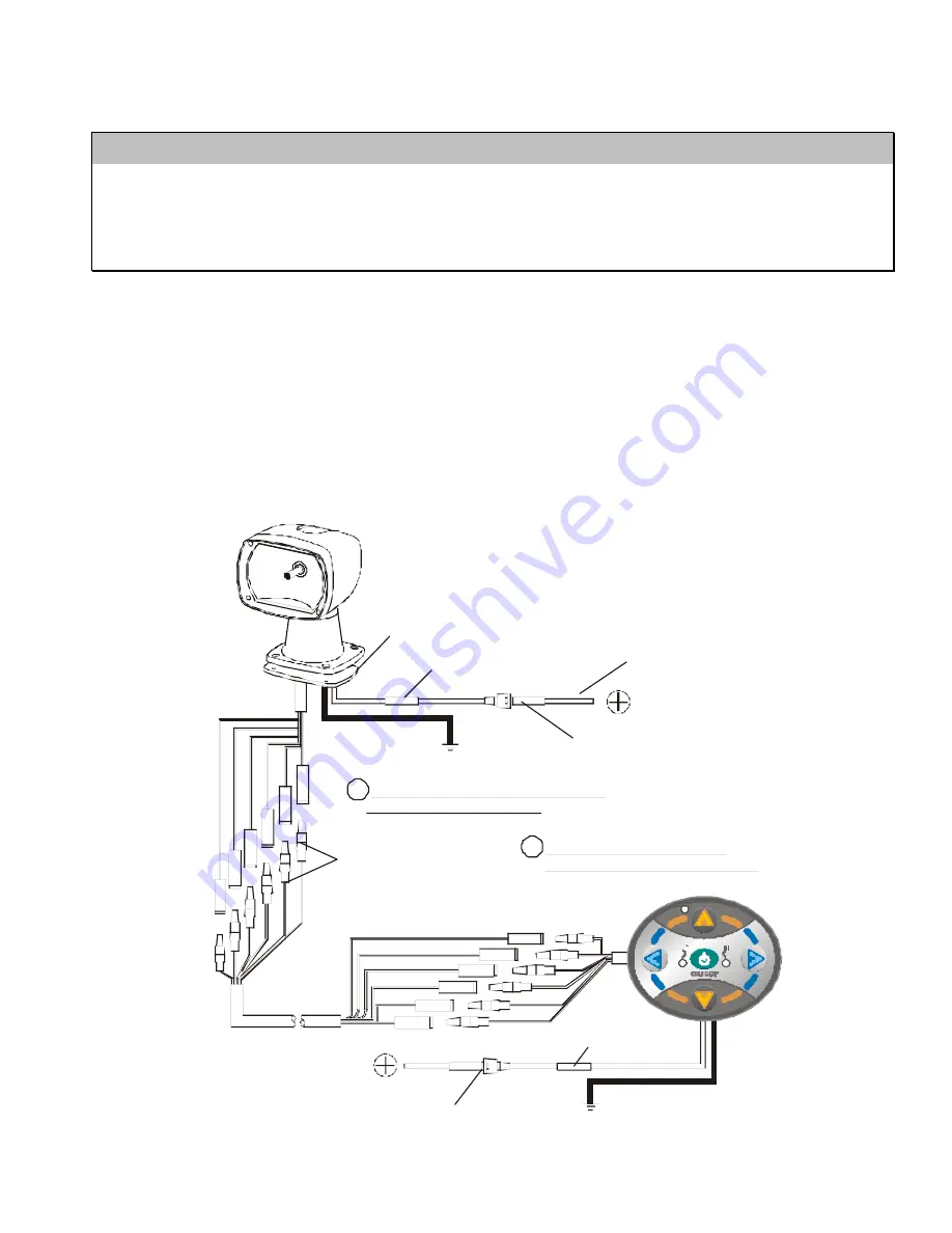
Complete the wiring connections as shown below: 


Foam Gasket

10-12 ga. Butt Connector

10 Amp Fuse 
(or circuit breaker)

     Black
12 volts DC

Red 
12 volts DC

1.


Connect Spotlight cable wires to SAME 

color wires of  provided cable

Cable Male Plugs
    on this end

2.


Connect control cable wires to

SAME color wires of provided cable

18-22 ga. Butt Connector

    Black
12 volts DC

      Red
12 volts DC

2 Amp
 Fuse

CONTROL
PANEL


Summary of Contents for 503A BEAMER

Page 1: ...3A BEAMER REMOTE CONTROL SPOT FLOOD LIGHT INSTALLATION AND OPERATION INSTRUCTIONS IMPORTANT READ THESE INSTRUCTIONS BEFORE INSTALLING AND USING THIS PRODUCT KEEP THESE INSTRUCTIONS FOR FUTURE REFERENC...

Page 2: ...signed for 12 volt operation only Tools and additional materials required Electric drill with 1 2 13mm 5 16 8mm and 3 16 5mm bits Wire crimping tool Phillips head screwdriver 2 7 16 11mm wrenches Non...

Page 3: ...wer tools 4 Install the foam gasket on to the base of the spot flood light making sure that all eight wires exit through the center hole in the gasket 5 Feed the eight wires coming out of the base of...

Page 4: ...not to scale make sure that the holes are horizontal to each other 1 5 38mm 3 0 76 5mm 2 Places 3 16 5mm hole hole 1 2 13mm reference 3 26 82 8mm reference 3 9 100 2mm 3 Feed all of the Control Panel...

Page 5: ...rectly to the main 12 volt DC accessory panel Install fuse and fuse holders as shown in diagram A 10 amp circuit breaker can be installed instead of an in line 10 amp fuse If the light will be less th...

Page 6: ...oodlight while it is operating DO NOT cover the light with a fabric cover or any other flammable material Accidental activation may result in a fire hazard DO turn the spotlight toward the control sta...

Page 7: ...R replace a blown fuse with a higher value fuse Most problems are caused by poor wiring connections Confirm that all wiring connections are accurate and well made Be sure that the spotlight and contro...

Page 8: ...rol panel If your light has a problem that is not described above contact the GUEST Co Service Department for assistance LIMITED WARRANTY For one 1 year from the date of original purchase The Guest Co...

Reviews: