28
11. Appendix A
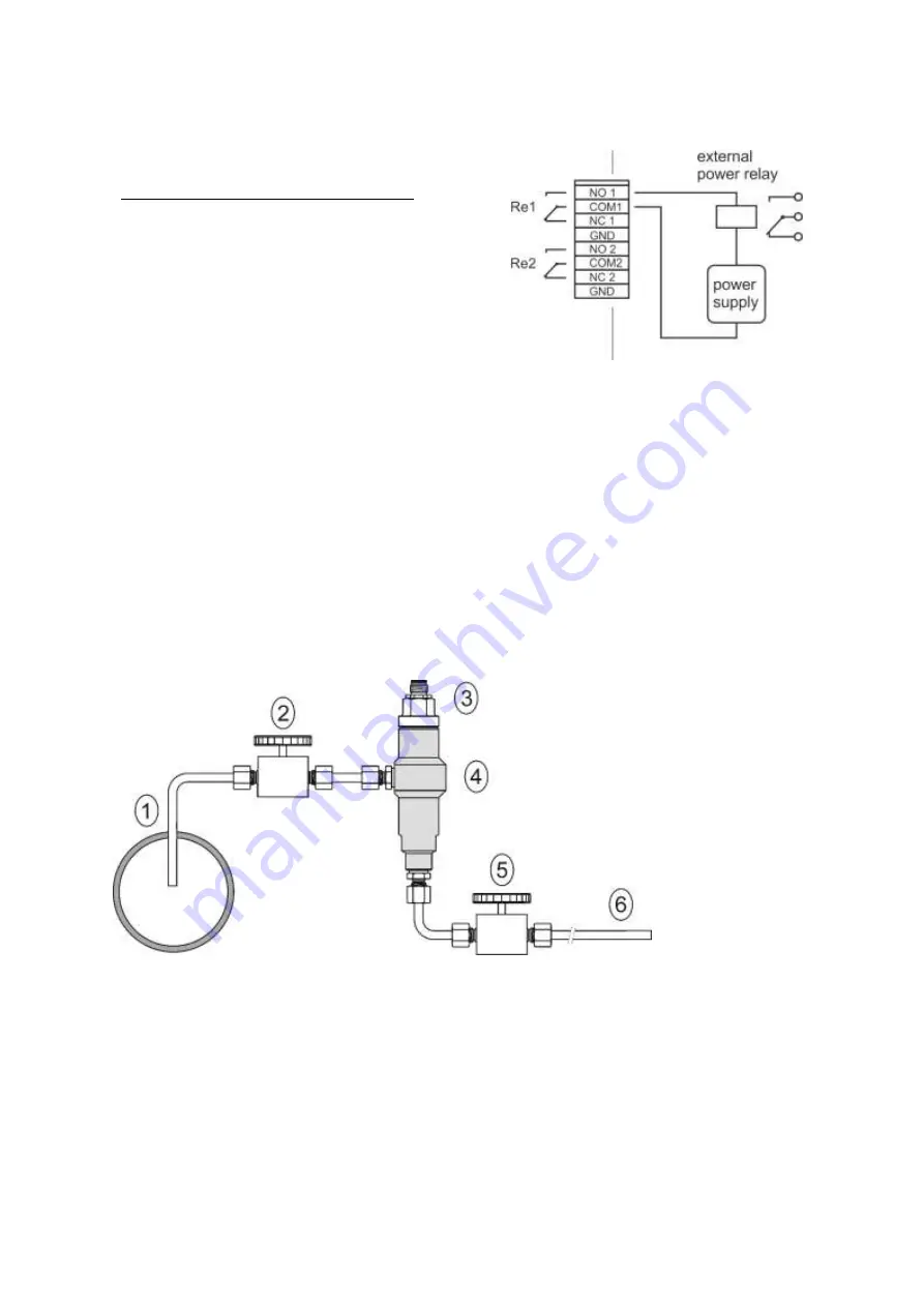
Connection of external power relay
Coil data chart of external power relay:
nominal voltage : max 50V
nominal power: max 60VA
current:
max 2A
12. Appendix B
The probe for measuring the moisture of compressed air should be placed directly on the pressure
pipelines to achieve higher measurement accuracy and fast response times. But they are cases where
such placement is not possible. The reason is the high air speed, high temperature, high pollution,
small diameter pipes, etc. Such situation can be solved by placing the probe into the flow measuring
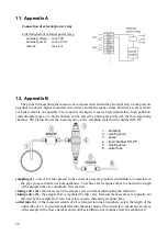
chamber. The picture shows the basic layout of the sampling system with chamber SH- PP.
1 ….sampling
2 ….closing valve
3 ….probe
4 ….flow chamber SH
-PP
5 ….closing valve
6 ….outlet tube
sampling (1)
- end of the tube placed in the centre of pressure pipelines (distribution of moisture in
the pipe cross-section is not homogeneous). To achieve fast response times to shorten the length
of the sample tubes to a minimum (few meters).
closing valve (2) -
allows access to the sample system without interrupting the main line
closing valve (5) -
the sample flow is regulated by this valve. Measurement accuracy is typically not
affected by the sample flow rate, but at low speeds, increasing response time.
outlet tube (6) -
if the measured sample of air is released into the atmosphere, select the length of the
outlet tube of 1.5 m (recommended for tube diameter 6mm). The reason is to ensure the accuracy
of the sample in the flow chamber and avoid back diffusion of moisture from the ambient air.
.


