8
5.2. Relay outputs
Regulator is equipped with two relay outputs. It is possible to assign any input or computed value
or “Far condition” (see chapter
at page 18) to each relay, to set comparing alarm limit, if the
relay may close if measured value is higher (Hi) or lower (Lo) than preset limit, delay for while must
be preset condition true before relay close its contact and hysteresis for return to open status. For
binary inputs: if it is preset to „HI“ then output relay is closed when input contact is opened, if it is
preset to „Lo“ then output relay is closed when input contact is closed. Each relay status is indicated
with LED diode and shown on LCD with corresponding symbols „
“ or „
“.
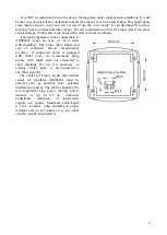
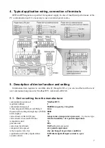
Terminal block for connecting the relays is equipped with terminals GND, which are connected
to the power supply of the device (see chapter “
Typical application wiring, connection of terminals”)
.
When you need to use relays to switching the voltage identical with the supply voltage of the device,
you can use jumpers J1 and J2 for interconnection the power supply of the device directly with the
common contacts of the relays.
This modification is used in devices with serial number higher
than 16981000
(the wiring diagram of the relay contacts for devices with serial number lower than
16981000 is given in the “
”).
The devices are equipped with two relays that are not intended for direct switching power circuits
or mains voltage. If necessary, use suitable type of external relay (an example of wiring is given in
the “
).
5.3. Binary inputs
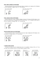
It is possible to read status of three galvanically not isolated binary inputs. It is possible to connect
“open contact” or external voltage. Auxiliary power U terminal can be used to supplying
of
external sensors and
detectors.
Visualization of binary inputs is done by three LED diodes placed on
the left side from LCD. Green one represents input Binary 1, yellow input binary 2 and red input
binary 3. If binary input is not connected or is without any signal, then binary input is interpreted as
„1“, when input contact is closed (connected input), then binary input is interpreted as „0“. For each
binary input there is possible to set indication LED function – if is lighting when binary input is closed
or opened. Binary input status can be assigned to any of output relays. It is possible to choice if output
relay is closed or opened when binary input is closed/opened.
5.4. Actual regulator preset
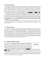
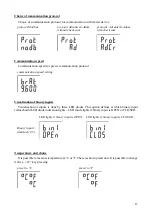
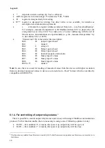
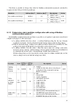
It is possible to display actual regulator preset on its LCD display by
pressing of „
“ key. If „Output relay alarm condition configuration with
using of Modbus communication protocol“ is active (Remote Control), then
device’s LCD display shows text „bloc“. It means, device’s keyboard is
disabled for time of remote control (setting change), see chapter
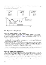
19. LCD shows information about Relay1 and then Relay2 setting step by
step. Information about Relay1 are indicated with symbol „
“, for Relay2 with symbol „
“ (at right top corner of LCD). It is possible to edit parameters after pressing „
SET
“
key and entering of correct password „
PASS
“ – see chapter „
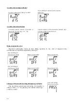
Change of “Password for setting
at page 12. Following examples are for Relay1 setting, similarly are displayed
values for Relay2. Pressing of „
ESC
“ key ends this mode and switch to actual value displaying, the
same occur if more than 20 s is not pressed any key.


