Section 5
TM6564-C-00
26 April, 2011
5-2
5.4.
LOCATING THE RELAY CHANNELS
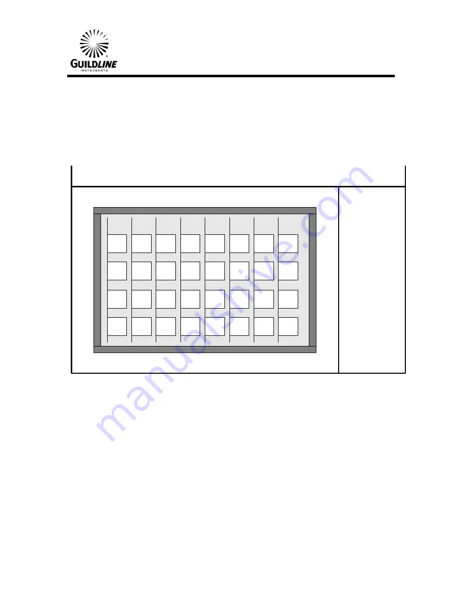
When the cover of the isothermal box is removed, the relay boards can be seen. Each
board holds four CHANNEL relays. Refer to figure 5.1. The CHANNEL relays are along
the top of the board for easy access. The first relay is at the end of the board closest to the
rear panel. Channels one through four are on the board closest to the power transformer.
The next board has channels five through eight and so on.
6664C Rear Panel
A-Line Relays on Top
B-Line Relays on Bottom
16
15
14
13
12
11
10
9
8
7
6
5
4
3
2
1
16
15
14
13
12
11
10
9
8
7
6
5
4
3
2
1
High Relays
Low Relays
Figure 5-1 Relay Locations (Top View)
6564 REAR PANEL


