background image


Section 6


TM6564-C-00 
26 April, 2011 


6-8 


+

 3

.3
F

+

 3

.3
F

+

 3

.3
F

+

 3

.3
F

+

 3

3

 
F

 4

.7

 
H

IN

T

E

R

F

A

C

E

 B

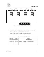
O

A

R

D

3

2

0

-0

0

7

E

F3
7

9

U1

F3
7

9

U2

F3
7

9

U3

L

S1
4

U5

L

S1
3

2

 U6

 U7

 U8

L

S1
2

3

U16

L

S1
2

3

U15

L

S0
5

U14

L

S1
4

U11

P

R

O

M

U10

L

S6
8

8

U9

BUS

ADRESS

RN1

C2

C10

C7

C

1

1

C

1

2

C

1

3

C4

C3

C5

C8

CR4

RN2

CR2

RN3

C9

L1

C1

S1

RN5

C6

CR5

RN4

CR3

L

S1
6

4

U4

L

S1
3

2

L

S1
3

2

S

N

7

5

1

6

0

B

N

U12

S

N

7

5

1

6

1

B

N

U13


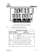
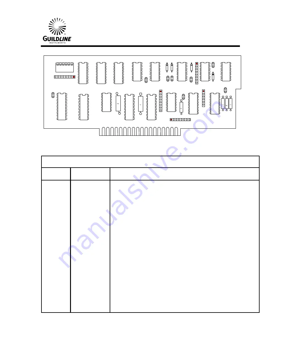
INTERFACE BOARD

 COMPONENT LOCATIONS 


INTERFACE BOARD CIRCUIT PARTS LIST 

 CIRCUIT 

PART 


PARTS 

 DESIGN. 

NUMBER 


DESCRIPTION 

 C3,4,5,6 

16-01 

  CAPACITOR, FXD, 470 pf 50VDC, 5%, Monolithic 

 C1,2,7,8 

16-02 

  CAPACITOR, FXD, .01 uFd 50VDC, 10%, Monolithic 

 C9 

18-04 

  CAPACITOR, FXD, .33 uFd 10VDC, 10%, Tantalum 

 C10-13 

18-02 

  CAPACITOR, FXD, 3.3 uFd 15 VDC, 10%, Tantalum 

 CR2-5 

22-01 

  DIODE, 50VPIV, 200mA, 1N4150 

 L1 

46-01 

  INDUCTOR,FXD,4.7uH 

 RN1,3 

68-02 

  RESISTOR, NETWORK,7x10Kohm, 2% Cermet, SIP 

 RN2 

68-11 

  RESISTOR, NETWORK,4x470Kohm, 2% Cermet, SIP 

 RN4 

68-12 

  RESISTOR, NETWORK,4x2.2Kohm, 2% Cermet, SIP 

 RN5 

68-08 

  RESISTOR, NETWORK,5x100Kohm, 2% Cermet, SIP 

 S1 

31-05 

  SWITCH,SIP,6 Position 

 U1-3 

20-18 

  IC,QUAD D-Type FLIP-FLOP, LS379 

 U4 

20-16 

  IC,8-BIT SHIFT REGISTER, LS164 

 U5,11 

20-05 

  IC,HEX Schmitt Trigger INVENTOR,, LS14 

 U6,7,8 

20-11 

  IC,QUAD 2-Input Schmitt Trig NAND, 74LS132 

 U9 

20-19 

  IC,8-BIT MAGNITUDE COMPARATOR, LS688 

 U10 

20-20 

  MEMORY CIRCUIT, 512x8,Programed 

 U11 

20-23 

  TRANSCEVER, IEEE-488, SN75160BN 

 U12 

20-24 

  TRANSCEVER, IEEE-488, SN75161BN 

 U14 

20-03 

  IC,HEX INVENTOR, Open Col. Output, LS05 

 U15,16 

20-10 

 IC,DUAL Monostable MULTIVIBRATOR, LS123 

Summary of Contents for 6564

Page 1: ...etary to Guildline Instruments Limited They are to be used only as a guide to the operation and maintenance of the equipment with which this manual was issued and may not be duplicated or transmitted by any means either in whole or in part without the written permission of Guildline Instruments Limited TM6564 C 00 26 April 2011 ...

Page 2: ......

Page 3: ...e Neither Guildline Instrument Limited nor any of its employees shall be liable for any direct or indirect special incidental or consequential damages arising out of the use of this product No other warranty is expressed or implied SAFETY PRECAUTIONS This product has been designed and tested in accordance with IEC1010 1 EN61010 1 including amendment 1 1995 for insulation category II use Use of thi...

Page 4: ...2 3 LOCATION 2 1 3 OPERATION 3 1 3 1 FRONT PANEL CONTROLS AND INDICATORS 3 1 3 2 REAR PANEL CONNECTIONS 3 2 3 3 FRONT PANEL OPERATION 3 3 3 4 ADDRESS SELECTION 3 3 3 5 OPERATION FROM INTERFACE BUS 3 5 3 6 SAMPLE PROGRAMS 3 6 3 7 REMOTE LOCK 3 7 3 8 STANDARD PROTECTION FOR MULTIPLE SCANNERS 3 7 4 THEORY OF OPERATION 4 1 4 1 INTRODUCTION 4 1 4 2 HIGH ISOLATION LOW NOISE DESIGN 4 1 4 3 LOGIC CIRCUITS...

Page 5: ...ODIC MAINTENANCE 5 1 5 2 UNSTABLE READINGS 5 1 5 3 RELAY FAILURES 5 1 5 4 LOCATING THE RELAY CHANNELS 5 2 6 CIRCUIT DIAGRAMS AND REPLACEMENT PARTS LIST 6 1 6 1 INTRODUCTION 6 1 6 2 ORDERING INFORMATION 6 1 6 3 CIRCUIT DIAGRAMS AND PARTS LISTS 6 2 7 DECLARATION OF CONFORMITY 7 1 ...

Page 6: ...011 iv TABLE OF FIGURES FIGURE 1 1 HIGH RESISTANCE SCANNER GUILDLINE MODEL 6564 1 1 FIGURE 3 1 FRONT PANEL GUILDLINE MODEL 6564 3 1 FIGURE 3 2 REAR PANEL GUILDLINE MODEL 6564 3 2 FIGURE 4 1 FUNCTIONAL DIAGRAM OF SCANNER 4 2 ...

Page 7: ...TM6564 C 00 26 April 2011 v LIST OF TABLES TABLE 3 1 BUS ADDRESS 3 4 ...

Page 8: ... The switches used are latching relays requiring only a few millisecond pulses to actuate Several systems are used to protect the devices connected to the scanner from being damaged by operator error or scanner failure It can be operated from the front panel or by commands sent over the General Purpose Interface Bus The 6564 has been designed in a modular fashion in banks of 8 channels It is possi...

Page 9: ... Warm the scanner up for 2 hours min SCANNER CONTROL Local using front panel push buttons Remote via IEEE 488 bus interface included RELAY CONTACT RATINGS Life greater than 10 000 000 cycles at low levels Current 2 amps maximum at 10 volts Voltage switched 100 volts maximum at 1 milliamp Voltage non switched 1000 volts max for terminal inputs CAUTION reduce voltage before actuating relays NOTE whe...

Page 10: ...connected in parallel with other scanners cascaded in a large system to protect standards from being shorted together 1 4 REFERENCE STANDARD PROTECTION SYSTEMS Three systems are used to help protect standards from being damaged due to scanner failure or operator error These systems are described briefly below See Theory of Operation Section for complete description a The relays are driven from a d...

Page 11: ...0 WARNING BEFORE SWITCHING ON THIS INSTRUMENT THE PROTECTIVE TERMINAL OF THIS INSTRUMENT MUST BE CONNECTED TO A PROTECTIVE EARTH CONTACT THE POWER LINE CORD SUPPLIED WILL PROVIDE THE PROTECTIVE GROUNDING WHEN INSERTED INTO A SOCKET OUTLET PROVIDED WITH AN EARTH CONTACT THE PROTECTIVE ACTION MUST NOT BE NEGATED BY THE USE OF AN EXTENSION CORD OR ADAPTOR WITHOUT A PROTECTIVE GROUNDING CONDUCTOR 2 3 ...

Page 12: ...sh buttons when depressed at the same time that either the A LINE or the B LINE push button is depressed will cause the corresponding relay to close 4 LINE A lights indicates which LINE A relay is closed 5 REMOTE light is illuminated when the scanner is in bus control The front panel push buttons are inoperative 6 LOCAL Light is illuminated when the scanner is in front panel local control 7 Cover ...

Page 13: ...T Connect to source input of teraohmmeter 3 LOW CURRENT OUTPUTS Connect to low current input of teraohmmeter 4 GUARD Connected to chassis at relay isothermal box 5 PROTECT CIRCUIT Connect to same terminals on other scanners Provides protection for standards in a multiple scanner system See Section 3 9 for details 6 INTERFACE BUS IEEE 488 bus connector used to connect scanner to controller 7 5V DC ...

Page 14: ...ush buttons can be depressed in either order and the end result will be the same that is any previously closed relay will be opened and the desired relay will be closed The important thing is that two push buttons must be pressed for any relay to close 3 4 ADDRESS SELECTION The IEEE 488 bus address of the scanner is selected by the DIP switches located on the interface board under the top cover Th...

Page 15: ... 0 1 0 0 1 09 J 0 1 0 1 0 10 K 0 1 0 1 1 11 L 0 1 1 0 0 12 M 0 1 1 0 1 13 N 0 1 1 1 0 14 O 0 1 1 1 1 15 0 P 1 0 0 0 0 16 1 Q 1 0 0 0 1 17 2 R 1 0 0 1 0 18 3 S 1 0 0 1 1 19 4 T 1 0 1 0 0 20 5 U 1 0 1 0 1 21 6 V 1 0 1 1 0 22 7 W 1 0 1 1 1 23 8 X 1 1 0 0 0 24 9 Y 1 1 0 0 1 25 Z 1 1 0 1 0 26 1 1 0 1 1 27 1 1 1 0 0 28 1 1 1 0 1 29 1 1 1 1 0 30 Table 3 1 Bus Address 6 5 4 3 2 1 Position 1 away from boar...

Page 16: ...des designating the relay and then a carriage return line feed For example using an HTBasic computer the statement OUTPUT 724 A01 Would cause any relay on the CHANNEL to be cleared and then relay number 1 to be closed In this example 7 is the controller IO address 24 is the scanner address and A01 is the code for relay 1 on the CHANNEL Note that each actuation must be a separately addressed statem...

Page 17: ...EARS CHANNEL 90 END Note A Wait of at least 200 milliseconds is required between relay actuations to allow time for the relay circuits to actuate The second program example has exactly the same result as the first program listed above but uses string output statements The formatted output statement is used to assure the first character that the scanner sees after the address is the line code and t...

Page 18: ...ion circuit prevents more than one relay on either scanner CHANNEL from being closed at the same time that prevents standards from being shorted together Each relay has a contact that closes when the relay is in the open position These contacts must all be closed relays open for the logic circuit to allow a close pulse to be sent out This protection can be extended to more than one scanner in a la...

Page 19: ...a heavy machined aluminum box This isothermal enclosure helps to maintain a uniform temperature at each of the relay contacts and provide an excellent EMI shield for low current measurement The printed circuit edge connectors carry only the relay coil and panel light circuits All the channel input lines are soldered to the relay boards directly to prevent the thermal and noise voltages caused by c...

Page 20: ...tivated for any possible combination of the six input lines If a failure should occur in the bus interface encoder or selector circuits or if an incorrect message is sent over the bus no devices will be damaged because only one relay can be closed 32 to 5 Line Encoder A B Selector BUS Inter Face BUS Push Button Selector 6 TO 64 Line Decoder and Relay Drivers Logic Control Circuit A Line B Line GPI...

Page 21: ... already closed These series protection lines are brought out to terminals on the rear panel Thus if more than one scanner is used in a large system and these terminals are connected together all units in the system will be protected The third protection mechanism to protect devices from damage is not shown on the diagram but is part of the control logic circuit This is the requirement that two pu...

Page 22: ...als for best contact quality and reliability Scanner channels that are used less than once a month may develop a film on the relay contacts The relay contacts are wiped clean each time they are used however if a relay is not used for a while the film may not be wiped clean with only one closing of the relay Infrequently used relays should be switched on and off a few times before use This can be d...

Page 23: ...of the board for easy access The first relay is at the end of the board closest to the rear panel Channels one through four are on the board closest to the power transformer The next board has channels five through eight and so on 6664C Rear Panel A Line Relays on Top B Line Relays on Bottom 16 15 14 13 12 11 10 9 8 7 6 5 4 3 2 1 16 15 14 13 12 11 10 9 8 7 6 5 4 3 2 1 High Relays Low Relays Figure...

Page 24: ...ircuit diagram a component location diagram and a parts list There is also a list of general parts that are located on the chassis and the rear panel 6 2 ORDERING INFORMATION To obtain parts directly from the factory send an order to the address shown on page 7 1 of this manual Identify parts by their part number as shown on the following pages Include the instrument model and serial numbers as we...

Page 25: ... Tellurium copper gold flashed 2 51 02 LOW THERMAL BINDING POST RED Tellurium copper gold flashed 3 51 03 BINDING POST MOUNTING BASE 4 51 04 TERMINAL BLOCK 4 CONDUCTOR 5 50 11 IEEE 488 BUS CONNECTOR MOTHER BOARD NOT SHOWN 320 000 Mother Board 50 04 PC CONNECTOR 15 PIN 50 05 PC CONNECTOR 18 PIN 50 06 PC CONNECTOR 22 PIN 50 09 PC CONNECTOR 30 PIN 51 04 FLAT CABLE CONNECTOR 24 PIN 81 14 FLAT CABLE 28...

Page 26: ... R1 R2 68 05 RESISTOR NETWORK 9x180 ohm Cermet SIP R3 R4 69 03 RESISTOR FXD 1Kohm 0125W 1 Met film A LINE S17 B LINE S18 A1 LED B1 LED LOCAL LED REMOTE LED S2 S1 S3 S4 S5 S6 S7 S8 S9 S10 S11 S12 S13 S14 S15 S16 B2 B3 B4 B5 B6 B7 B8 B9 B10 B11 B12 B13 B14 B15 B16 A2 A3 A4 A5 A6 A7 A8 A9 A10 A11 A12 A13 A14 A15 A16 CONNECTOR A CONNECTOR B CONNECTOR D CONNECTOR C MODEL 164B 6664B HI LOW HI LOW ...

Page 27: ...lay B4 LED 180 Ohm To A5 Relay A5 LED 180 Ohm To B5 Relay B5 LED 180 Ohm To A6 Relay A6 LED 180 Ohm To B6 Relay B6 LED 180 Ohm To A7 Relay A7 LED 180 Ohm To B7 Relay B7 LED 180 Ohm To A8 Relay A8 LED 180 Ohm To B8 Relay B8 LED 180 Ohm To A9 Relay A9 LED 180 Ohm To B9 Relay B9 LED 180 Ohm To A10 Relay A10 LED 180 Ohm To B10 Relay B10 LED 180 Ohm To A11 Relay A11 LED 180 Ohm To B12 Relay B12 LED 180...

Page 28: ...3 6 7 18 01 CAPACITOR FXD 1 uFd 15VDC 10 Electrolytic C11 18 04 CAPACITOR FXD 33 uFd 10VDC 10 Electrolytic L1 46 01 INDUCTOR FXD 4 7uH RN1 68 06 RESISTOR NETWORK 9x47Kohm 2 Cermet SIP RN2 3 4 5 6 68 03 RESISTOR NETWORK 9x10Kohm 2 Cermet SIP RN7 68 10 RESISTOR NETWORK 4x1Kohm 2 Cermet SIP U1 2 20 06 IC DUAL 4 Input NAND Gate 74LS20 U3 4 9 20 10 IC DUAL Monostable MULTIVIBRATOR 74LS123 U5 8 20 02 IC...

Page 29: ...LECTOR A B 5 6 13 3 10 11 14 2 Hi Clear Hi 1 16 Hi Trig Hi A FROM BUS INTERFACE LO REMOTE HI 1 16 TO CLOSE BOARDS B SERIES LINE A SERIES LINE TO RELAY BOARDS B A B PROTECT A PROTECT TO REAR PANEL 2 1 9 K 10 L 5 6 7 4 A 1 16 B 1 16 A 17 32 B 17 32 B CLOSE A CLOSE B CLEAR A CLEAR TO CLEAR BOARD H 7 6 3 20 ms 20 ms S1 S2 S3 S4 R S 14 15 F 5 E D 6 HI CLEAR HI TRIG HI A P N 12 13 D1 D2 D3 D4 M 11 G Y0 ...

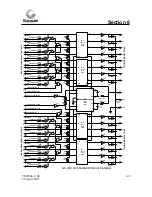
Page 30: ...13 2 7 10 15 1 9 Q1 Q2 D1 D2 D3 D4 CLK G 4 5 2 7 12 13 9 1 D1 D2 D3 D4 CLK G Q4 Q3 Q2 Q1 4 5 12 13 9 1 15 10 7 2 A1 A2 A3 A4 Y1 Y2 Y3 Y4 Y5 Y6 17 16 12 11 9 8 7 6 2 3 4 5 COM U5 1 13 12 11 2 3 4 5 6 U8 6 RN6 470 C3 470pF CR2 U5 13 12 1 2 CR4 RN6 470 C5 470pF U6 8 10 9 5V C 15 RN7 100K C11 3 3 F C12 3 3 F U16 LS123 Handshake Timeout A C R C CLR _ Q 6 10 12 7 9 5V B 11 C7 01 F U15 LS123 Triger Gen A...

Page 31: ...10 Tantalum C10 13 18 02 CAPACITOR FXD 3 3 uFd 15 VDC 10 Tantalum CR2 5 22 01 DIODE 50VPIV 200mA 1N4150 L1 46 01 INDUCTOR FXD 4 7uH RN1 3 68 02 RESISTOR NETWORK 7x10Kohm 2 Cermet SIP RN2 68 11 RESISTOR NETWORK 4x470Kohm 2 Cermet SIP RN4 68 12 RESISTOR NETWORK 4x2 2Kohm 2 Cermet SIP RN5 68 08 RESISTOR NETWORK 5x100Kohm 2 Cermet SIP S1 31 05 SWITCH SIP 6 Position U1 3 20 18 IC QUAD D Type FLIP FLOP ...

Page 32: ...13 2 7 10 15 1 9 Q1 Q2 D1 D2 D3 D4 CLK G 4 5 2 7 12 13 9 1 D1 D2 D3 D4 CLK G Q4 Q3 Q2 Q1 4 5 12 13 9 1 15 10 7 2 A1 A2 A3 A4 Y1 Y2 Y3 Y4 Y5 Y6 17 16 12 11 9 8 7 6 2 3 4 5 COM U5 1 13 12 11 2 3 4 5 6 U8 6 RN6 470 C3 470pF CR2 U5 13 12 1 2 CR4 RN6 470 C5 470pF U6 8 10 9 5V C 15 RN7 100K C11 3 3 F C12 3 3 F U16 LS123 Handshake Timeout A C R C CLR _ Q 6 10 12 7 9 5V B 11 C7 01 F U15 LS123 Triger Gen A...

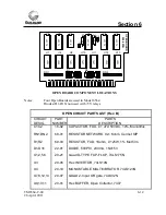
Page 33: ...tes Two close boards are used in Model 6564 Diodes CR1 CR32 not used with 5V relays CLOSE CIRCUIT PARTS LIST CIRCUIT PART PARTS DESIG NUMBER DESCRIPTION C1 C2 16 02 CAPACITOR FXD 01 uFd 50VDC 10 Monolithic R1 69 03 RESISTOR FXD 1Kohm 0125W 1 Met film CR1 CR32 22 01 DIODE 50VPIV 200mA 1N4150 U1 2 4 5 20 22 3 TO 8 LINE DECODER 74LS138N U3 20 07 QUAD 2 Input OR gate 74LS32N U6 U11 20 01 Hex BUFFER Op...

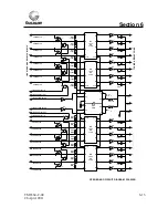
Page 34: ...NTACTS 3 5 U13 1 2 RN6 2 2k RELAY CHANNEL 1B LED 6 U3 38 RN6 2 2k RELAY CHANNEL 2B LED 12 U3 4 0 RN6 2 2k RELAY CHANNEL 3B LED 2 U15 42 RN6 2 2k RELAY CHANNEL 4B LED 4 U15 44 RN7 2 2k RELAY CHANNEL 5B LED 6 U15 46 RN7 2 2k RELAY CHANNEL 6B LED 12 U15 47 4 8 RN7 2 2k RELAY CHANNEL 7B LED 10 U15 5 0 RN7 2 2k RELAY CHANNEL 8B LED 8 U8 52 U12 CR11 1 2 U4 CR9 13 12 U4 CR10 11 10 U12 CR12 3 4 U12 CR13 5...

Page 35: ...not used with 5V relays OPEN CIRCUIT PARTS LIST Rev B CIRCUIT PART PARTS DESIG NUMBER DESCRIPTION C1 C2 16 02 CAPACITOR FXD 01 uFd 50VDC 10 Monolithic RN1 RN2 68 01 RESISTOR NETWORK 9x1 Kohm Cermet SIP R1 R2 69 03 RESISTOR FXD 1Kohm 0125W 1 Met film D1 D16 22 01 DIODE 50VPIV 200mA 1N4150 U1 2 5 6 20 21 Quad D TYPE FLIP FLOP 74LS175N U3 20 05 Hex INVERTOR 74LS14N U4 20 10 MONOSTABLE MULTIVIBRATOR 7...

Page 36: ..._ Q _ Q _ LINE B LEDS AND RELAY CONTACTS 3 U12 1 2 CHANNEL 1B 15 CHANNEL 2B S CHANNEL 3B 16 CHANNEL 4B T CHANNEL 5B 17 CHANNEL 6B U CHANNEL 7B 18 CHANNEL 8B Y U11 CR11 1 2 U10 CR9 13 12 U10 CR10 11 10 U11 CR12 3 4 U11 CR13 5 6 U11 CR14 13 12 U11 CR15 11 10 CLK CLR LINE B PROTECT OUT LINE B PROTECT IN RN2 1000 RN2 1000 RN2 1000 RN2 1000 RN2 1000 RN2 1000 RN2 1000 RN2 1000 U7 U7 U7 4 5 6 3 2 1 8 10 ...

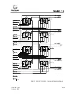
Page 37: ...t boards are used depending on the model 3 These boards are located under the top of the isothermal box RELAY BOARD PARTS LIST CIRCUIT PART PARTS DIAGRAM NUMBER DESCRIPTION All PARTS 49 04 RELAY LATCHING 2 AMP 5 VOLT OUTPUT A C P OUTPUT B C P INPUT 1 C P INPUT 2 C P INPUT 3 C P INPUT 4 C P 1A RELAYS 2A RELAYS 3A RELAYS 4A RELAYS 1B RELAYS 2B RELAYS 3B RELAYS 4B RELAYS ...

Page 38: ...LAYS 1B RELAYS 2B RELAYS 3B RELAYS 4B RELAYS 164B 6664B P INPUT 1 2B LIGHT 2B CLEAR 2B CLOSE 2A LIGHT 2A CLEAR 1B LIGHT 1A LIGHT 1B CLEAR 1A CLEAR 1ACLOSE 1B CLOSE 3B CLOSE 5 COM D 12 P 13 S R 14 15 K K 9 11 L 10 E H 5 7 6 F A C 1 3 2 B INPUT 2 INPUT 3 INPUT 4 LINE A LINE B 164B 6664B C 164B 6664B P 164B 6664B P 164B 6664B P 164B 6664B P 164B 6664B C 164B 6664B C 164B 6664B C 164B 6664B C 164B 666...

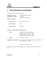
Page 39: ...del Numbers 6564 Product Options All Options Conforms to the following Product Specifications EMC EN50081 1 1992 EN55022 Class B EN50082 2 1992 IEC 801 2 1984 EN50082 2 1992 IEC 801 3 1984 EN50082 2 1992 IEC 801 4 1988 SAFETY EN 61010 1 1993 1995 Supplementary Information The Product herewith complies with the requirements of the EMC Directive 89 336 EEC January 10 1996 May 15 1997 Note The declar...

Reviews: