background image

G503152 - R00

2

1

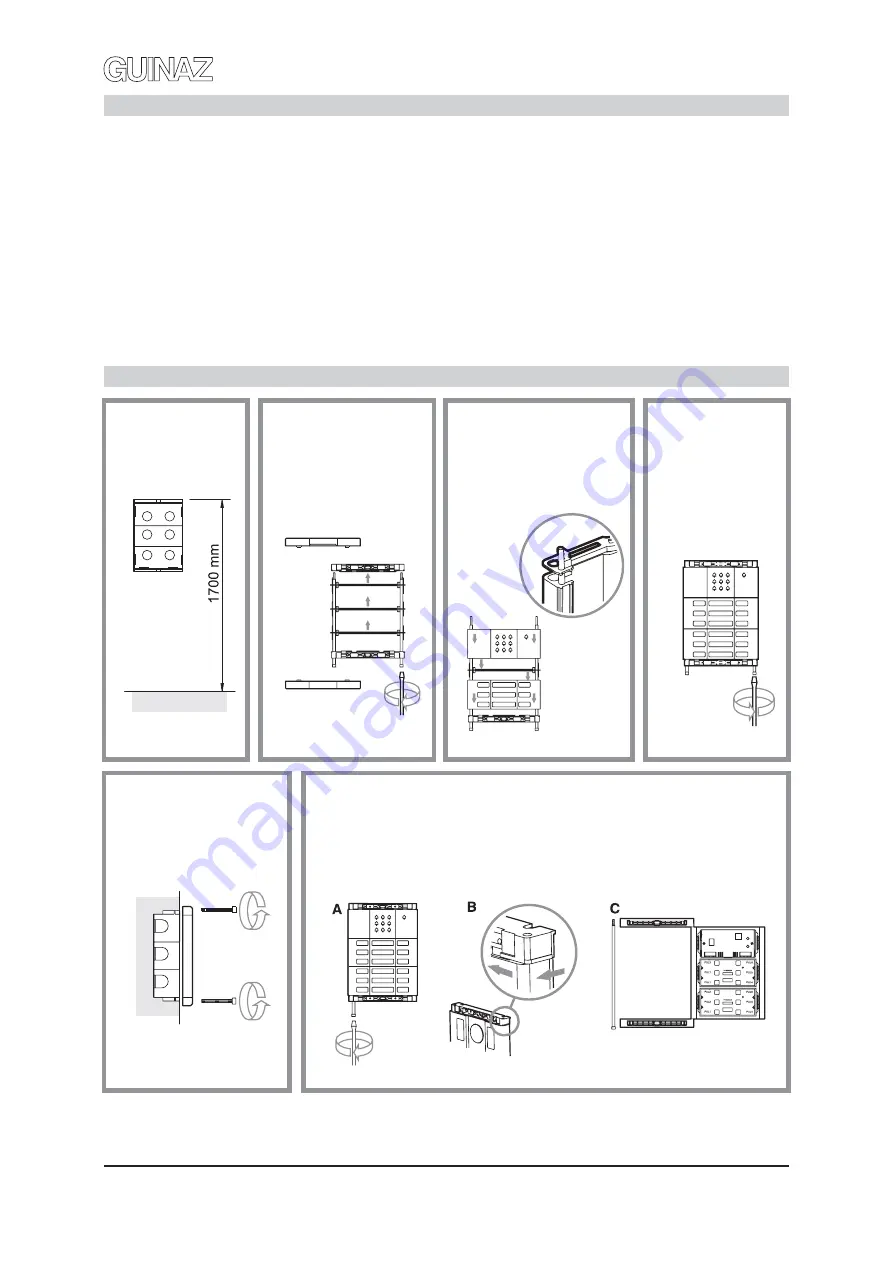
Coloque la caja

empotrable.

Assembly  the

flush  mounted

box.

Separe  las  tapas,

destornille  ambos

tornillos y extraiga las

juntas de módulos.

Separate the covers,

loosen both screws

and extract the joints

of the modules.

I n t r o d u z c a   l o s

módulos y juntas en el

mismo  orden  que

aparecen en la figura.

Insert  modules  and

joints in the same order

as in the figure.

2

3

4

5

6

Sujete la placa calle

m e d i a n t e   d o s

tornillos. 

Attach  the

street panel using two

screws.

Coloque el

marco superior

y apriete ambos

tornillos.

Put the upper

frame in place

and tighten both

screws.

Para  apertura  a  la  derecha. 

To  open  towards  the  right.

A. 

Suelte el tornillo izquierdo y afloje el derecho.

 Unscrew left screw

and loosen the right one.

B. 

Desplace la placa calle hacia la izquierda y frontalmente 1,5 mm.

Move the street panel 1.5 mm to the left and the front.

C.  

Gire la placa calle.

 Open the street panel.

INSTALACIÓN PLACA CALLE. 

INSTALLATION OF THE STREET PANEL.

ESPECIFICACIONES TÉCNICAS. 

TECHNICAL SPECIFICATIONS.

• Funcionamiento a 12 Vac.

• Generación de llamada electrónica bitonal ó

zumbador a 12Vac.

• Compatible con teléfonos de masas separadas

(ver tabla de equivalencias).

• Consumo máximo de abrepuertas: 2A.

• Operating at 12 VAC.

• Dual tone electronic call generated or 12 VAC

buzzer.

• Compatible with separate mass telephones (see

equivalence table).

• Maximum door opener consumption: 2A.

Summary of Contents for G1250

Page 1: ...GUÍA DE INSTALACIÓN INSTALLATION GUIDE GRUPO AUDIO UNIVERSAL REF G1250 UNIVERSAL AUDIO GROUP REF G1250 ...

Page 2: ...ws Para apertura a la derecha To open towards the right A Suelte el tornillo izquierdo y afloje el derecho Unscrew left screw and loosen the right one B Desplace la placa calle hacia la izquierda y frontalmente 1 5 mm Move the street panel 1 5 mm to the left and the front C Gire la placa calle Open the street panel INSTALACIÓN PLACA CALLE INSTALLATION OF THE STREET PANEL ESPECIFICACIONES TÉCNICAS ...

Page 3: ...ulsadores colocado en placa calle Extract the name card unit from the push button module of the street panel Separar translúcido de cristal Separate translucent glass part Introducción del tarjetero Insert the card Insertar en módulo de pulsadores hasta clipar Insert in the push button module until it clips in 1 2 3 4 Conexionado del grupo control a u d i o v e r t a b l a d e equivalencias y grup...

Page 4: ... 2 1 5 6 7 8 PUL TELÉFONO n TELEPHONE n TELÉFONO 1 TELEPHONE 1 F1318 CONEXIONES CON LATIGUILLOS DESDE G1250 A PRIMER MÓDULO DE PULSADORES Y DESDE ÉSTE AL SIGUIENTE ETC CONNECTIONS USING CONNECTORS FROM G1250 TO THE FIRST PUSHBUTTON MODULE FROM THIS TO THE FOLLOWING AND SO ON CABLE ALIMENTACIÓN POWER SUPPLY CABLE CABLE SEÑAL SIGNAL CABLE C02098 1 2 5 6 7 8 1 2 3 4 PUL 1 PUL 6 13 12 8 6 7 5 PUL 13 1...

Page 5: ...S DE USO INSTRUCTIONS FOR USE The installation of this device will be carried out as specified in this guide while applying the regulations in force Internal handling will only be performed by specialised personnel and always with the equipment disconnected from the mains Always keep the ventilation slits of this device clear under no circumstance will they be obstructed or covered G503152 R00 5 C...

Page 6: ...CITIFONIX BOGEN BTICINO BPT ATEA 8400 AUTELCO ATEA 702 ATEA ARFE AMPLIVOX 9 T 3 9 4 4 4 4 4 Z E E V 5 3 3 3 1 3 C C 3 6A 6 4 6 1 1 1 Z 3 4 5 1 3 2 4 4 LOW 6 C7 1 B 5 5 6 11 14 3 4 C 1 2 3 6 4 12 5 2 12 I 5 7 V 1 3 4 1 4 O 3 5 2 0 2 3 6 10 2 10 5 1 5 P1 T P1 5 10 7 5 2 1 6 6 6 6 1 B B 2 1 2 2 2 3 2 1 1 2 P A A 1 F P 4 3 3 6 MIC A 1 1 7 2 4 SPEC 2 2 B 7 2 2 5 1 3 7 3 5 5 P1 5 R 9 2 1 1 2 2 4 8 2 1 1...

Page 7: ...00 MICROVOX 11 9 C 7 4 4 7 4 4 1 4 T 1Z 4 V 1 10 S 6 1E 1 6 3 6 11 6 6 7 1 7 1 2 3 3 2 5 6 1 5 S 9 6 3 2 2 2 5 5 7 6 O O 3 4 T T 2 7 4 14 6 V 3 4 LL 2 7 5 1 7 3 6 1 6 1 13 3 7 2 6 15 2 3 0 8 T 4 2 2 U 3 6 4 3 2 3 2 0 2 5 6 1 4 T 4 6 3 4 3 2 2 1 2 9 2 EL 5 5 T 1 2 1 2 3 Z 1 4 1 8 9 8 8 3 2 5 2 2 2 4 2 2 4 8 7 8 1 1 4 3 3 2 1 4 4 M M 9 1 9 2 A 2 3 Z 11 5 4 5 12 3 1 1 M 1 1 1 1 5 A 3 5 T Z 8 T1 1 3 1...

Page 8: ...terminal blocks 1 2 12 VAC If there are problems with any of these outputs disconnect the PRIM cables wait for one minute and reconnect them Should the problem persist check the installation connections If these are correct the supply may be faulty Revisar conexión de cables 6 7 y configuración de J2 Verificar que los volúmenes de los potenciometros no estén al mínimo Check the connection of cable...

Reviews: