background image

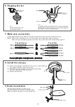
6-1.
Lift fan assembly onto
mounting bracket.

6-2.
Carefully lift fan assembly onto mounting bracket.
Rotate fan so that the groove on the ball engages
the ridge in the mounting bracket.

Mounting
Bracket

6. Hanging the fan

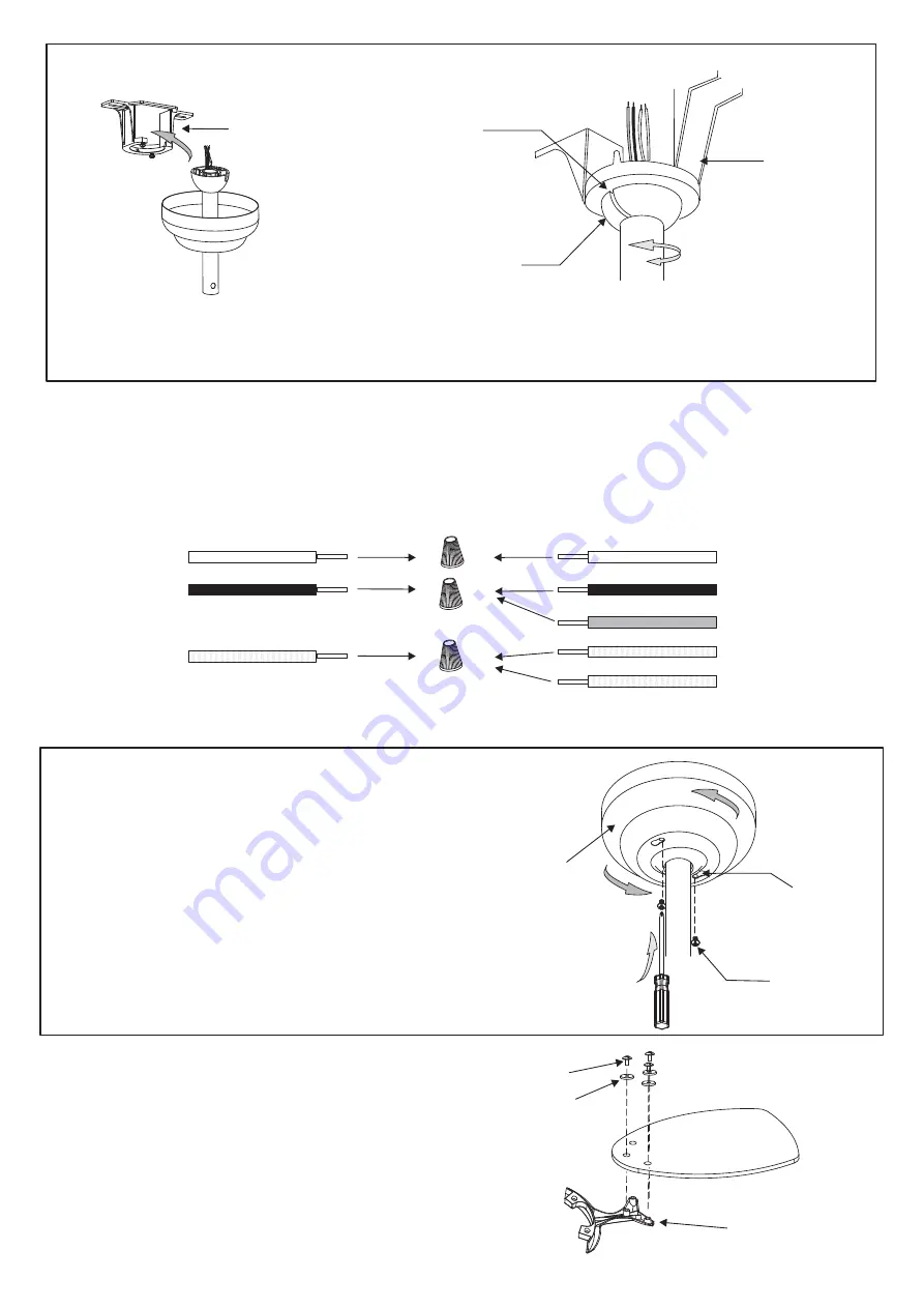
8-1.Push up the Canopy until the two screws on mounting bracket

are engaged with Key Holes in canopy.

8-2.Rotate the canopy slightly until the two screw heads

are in the small end of the Key Holes.

8-3.Tighten both screws.

Canopy

Key Holes

Screw

8. Install the canopy

P3

Attach blade to blade arm with screws
& rubber washers provided in hardware bag.
Make sure that all screws are firmly tightened.

9. Blades installation

Blade

Blade Screw

Rubber Washer

Blade Holder

Ridge

Ball Groove

Mounting
Bracket

7. Make wire connection

Follow diagram below and make sure that all exposed wires are secured inside wire nuts.

: Wires from house may vary in color and may not include ground wire ( green ).

After wiring is completed, gently push wires into junction box with nuts pointing upward.

Note

From House

White

Black

From Fan

White

Black

Blue

Secure with twist - lock wire nuts. (Included)

Secure with twist - lock wire nuts. (Included)

Green

Green

Green

( AC-N )

( AC-L )

( from downrod )

( from mounting bracket )

( for ground wire )

( for light kit )

(Motor-N)

(

-L)

Motor

Summary of Contents for 4YU26

Page 1: ... instructions carefully and be mindful of all warnings shown throughout WARNING READ AND SAVE THESE INSTRUCTIONS Follow these instructions carefully and be mindful of all warnings shown throughout 4YU26 Owners Manual UL R Total fan weight 3 5 KGS 4 5 LBS ...

Page 2: ... box a 4 x 2 1 8 deep METAL octagon box is required one UL listed as suitable for fan support The box and its supporting members must not be able to twist or work loose DO NOT USE PLASTIC BOXES Installation on a concrete ceiling should be performed by qualified personnel 5 Blades should be attached after motor housing is hung and in place Fan motor housing should be kept in carton until ready to b...

Page 3: ...rovided with the outlet box 2 3 4 Do not use existing mounting bracket replace it with new mounting bracket from box Do not use existing mounting bracket replace it with new mounting bracket from box Outlet Box Mounting Bracket 2 Insert the cross pin through yoke downrod and secure with cotter pin 3 Tighten both downrod set screws to further secure downrod then pull down the yoke cover to cover yo...

Page 4: ...h screws rubber washers provided in hardware bag Make sure that all screws are firmly tightened 9 Blades installation Blade Blade Screw Rubber Washer Blade Holder Ridge Ball Groove Mounting Bracket 7 Make wire connection Follow diagram below and make sure that all exposed wires are secured inside wire nuts Wires from house may vary in color and may not include ground wire green After wiring is com...

Page 5: ...nut 11 Make wire connections for light kit if this fan equips with light kit Terminal Block Style Loosen screws on Terminal Block first for accepting new wires from Light Kit 1 Insert white wire from Light Kit into terminal block extending from orange or white wire from fan and tighten by screw on terminal block 2 Insert black wire from Light kit into terminal block extending from brown or blue wi...

Reviews: