background image

 7

INSTALLATIONS

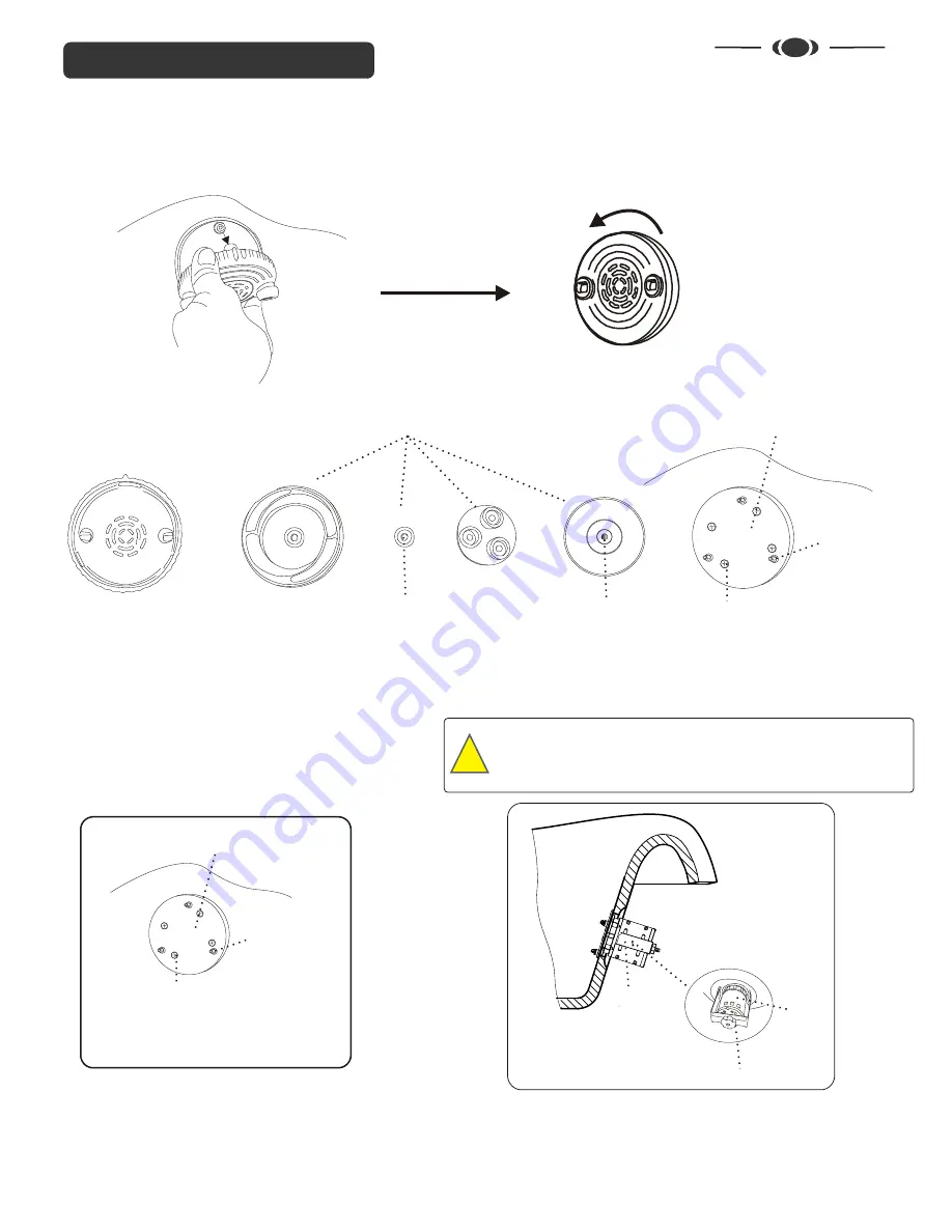
Cleanjet Unit Removal

Plate & Anchors located on tub/bowl wall

Impeller Housing

Top Plate

Wall

Ball

Washer

Anchor Pins

To remove the jet unit from tub/bowl. 
Gently pull out the jet unit from the anchor pins

To remove the jet unit components.
Turn the top plate counter-clockwise in the arrow direction

Jet Unit Components

To install the jet unit. Assemble all jet unit components in order as before removal, snap the jet unit onto the anchor pins located on tub/bowl
wall securely.
Note: All jet unit components must be assembled in sequence of order to avoid malfunction.

Screws

Base Plate & Anchors located inside tub/bowl

Wall

Anchor Pins

Screws

Option 1:

Remove the jet unit and


screws from the base plate in Fig.1

P

ull out the U-shape clamp and motor


behind the tub/bowl wall as shown in Fig.2

Option 2:

Remove the plastic cap lock at the end of the U-shape clamp


by turning counter-clockwise

Remove the U-shape clamp and push the


motor and base

plate forward


inside the tub/bowl as shown in Fig.2

Fig.1

Removing Base Plate and Motor

Clamp to hold
the motor and
seal the cap to tub

Fig.2

Plastic Cap Lock

Motor

Tub/Bowl

Jet motor components are located  behind the tub/bowl wall
Disconnect the foot-spa unit from any electrical source before
Disassemble the jet unit. All surface must be dry. Some jet
Components may contain sharp object and very hot after usage.

Warning

!!

Summary of Contents for 9600

Page 1: ...ications are subject to change without notice 2010 All rights reserved PLEASE SAVE THIS MANUAL FOR FUTURE REFERENCE OWNER MANUAL TM Cleanjet La Lili Chair 9600 FOOT SPA Chair 9700 TM Patent D610697 D600950 Patent Pending ...

Page 2: ...ety and Precautions INSTALLATIONS Attaching Seat Jet Assembly Plumbing Connections 1 2 Identifying Parts 3 4 7 8 9 Warranty Service 14 6 Owner Manual Operations and Use Cleaning Maintenance 10 11 12 13 Foot spa Clearance 5 ...

Page 3: ...cause severe damage to the unit as well as possible serious injury to the person BASIC PRECAUTIONS SHOULD ALWAYS BE OBSERVED INCLUDING THE FOLLOWING 1 Read and follow all instructions 2 DANGER To reduce the risk of injury do not permit children to use this unit unless they are supervised at all times 3 Use this unit only for its intended use as described in this manual Do not use attachments that ...

Page 4: ...ir a damaged cord OPERATION AND USE INSTRUCTIONS READ AND FOLLOW ALL INSTRUCTIONS 1 IMPORTANT At the end of the day ALWAYS turn the main power OFF 2 DANGER To reduce the risk of injury do not permit children to use this unit unless they are closely supervised at all times 3 CAUTION This unit should not be used by persons with open wounds cuts or sores on their feet or legs or by persons with poor ...

Page 5: ...Tub Glass Insert 2 Adjustable Footrest 3 Seat Cushion 4 Flip out Manicure Tray 5 Back Cushion Massage 6 Headrest Pillow 7 Wooden Armrest 8 Hand Spray Model ST700 20 9 Front Control Panel 10 Drain 11 Jet 2X 12 Drain Control 13 Water Control 14 Jet Control 9 Control Panel ...

Page 6: ...4 IDENTIFY YOUR FOOT SPA 1 2 3 Armrest can be raised up down Reclining Sliding 5 5 7 2 32 43 15 SEAT OPERATION SPA DIMENSION ...

Page 7: ...5 FOOT SPA CLEARANCE Wall 16 60 60 16 16 28 Foot spa 1 Center Center Foot spa 2 TYPICAL FOOT SPAS Clearance WALL CLEARANCE ...

Page 8: ...ALLATIONS Align the seat with the pre drilled holes on the base then tightly secure with the nuts and bolts provided Attach trays or remote stand to armrest with screws provided Attaching The Seat to The Base ...

Page 9: ...Base Plate Anchors located inside tub bowl Wall Anchor Pins Screws Option 1 Remove the jet unit and screws from the base plate in Fig 1 Pull out the U shape clamp and motor behind the tub bowl wall as shown in Fig 2 Option 2 Remove the plastic cap lock at the end of the U shape clamp by turning counter clockwise Remove the U shape clamp and push the motor and base plate forward inside the tub bowl...

Page 10: ...ring according to local codes The Cleanjets are 1 10 hp 120V 1 2 AMP 60OHZ A 15 amp GFI protected circuit must be used to supply power to the unit The roller back massage chair uses a 115V supply 5 Spa base should be anchored securely to the floor The base may be anchored through the opening in the back of the base wherever access is convenient for the installer 6 Hand Held sprayer Model ST700 20 ...

Page 11: ... Pump Installation GFI Outlet Required Existing Drain Pipe Minimum slope of 1 4 per foot to sewer line P Trap oo Fl r Wall 16 24 Foot spa Length Hot Cold Hoses Typical Gravity Drain Installation Existing Hot Cold Water Supply Back flow Preventer Vacuum Breaker Optional Existing Hot Cold Water Supply Back flow Preventer Vacuum Breaker Optional Check Valve ...

Page 12: ...base pump will run for approx 2 min Average time for drain 1 minute 5 9600 9700 chairs Shiatsu Roller back massage is equipped with a state of the art massage system The massage system is easy to use the remote has a one touch power that starts select your own massage You can also adjust the front to rear position of the chair and the reclining back By using the remote your client can adjust the b...

Page 13: ...g Knocking Width Lower Adjustment Incline Seat Forward Seat Backward Recline Intensity Air On Off Back Waist Kneading Upper Adjustment Speed Knocking Timing Upper Body Knead Flap Knead Flap Neck Shoulder Press Knock Back Waist Back Stretching Speed Width Seat On Off Intensity Mode Seat Forward Seat Backward Seat Incline Seat Recline Power LCD TT960 Manual ...

Page 14: ...lpool for 15 minutes drain and then wipe dry with clean soft cloth NOTE Cleaning or sanitizing is NOT disinfecting According to the Centers for Disease Control and Prevention CDC and the US Environmental Protection Agency EPA disinfecting occurs only when there is a reduction of pathogenic microbes at 99 999 Sanitizing is only a reduction of 99 9 Cleaning of whirlpool pedicure spas requires surfac...

Page 15: ...on top of the Magnet and the Back Plate so that the tab is slightly left from the top Turn the Top Plate clockwise until you hear a click sound Note there are 3 pegs on the back of the Back Plate the pegs which has small holes 1 18 of an inch should be aligned with the Top Plates tab after the click sound 6 Remount the Magnet Jet onto the pedicure bowl by aligning the pegs so that the tab is at th...

Reviews:

Related manuals for 9600