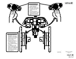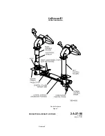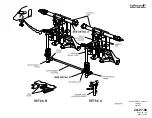
Each individual rudder pedal attaches to a pedal hanger arm that pivots
fore and aft on a lateral support tube. A rod assembly connected between
each pedal hanger arm and a vertical torque tube translates the fore and
aft movement of the pedal into rotational movement of the vertical torque
tube. An interconnect pushrod between the bases of the left and right
torque tubes interconnects the pilot’s and copilot’s rudder pedal sets. An
output crank attached to base of the right (copilot’s) torque tube ties the
rudder pedals to the rudder mechanical actuation system. A rotating lug-
type stop attached to base of the left (pilot’s) torque tube limits rudder
pedal travel when it contacts either one of two adjustable stop bolts.
Artificial feel forces are supplied by a spring bungee attached to the rudder
actuator input cable sector. The bungee provides a resistant force
proportional to rudder pedal displacement.
B. Mechanical Actuation System:
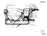
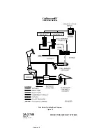
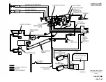
(See Figure 12.)
Rudder pedal inputs are transmitted rearward through a system of push-
pull rods, bellcranks, cables and a sector assembly to an input cable sector
near the base of the rudder in the tail compartment. As the right torque tube
rotates, its output crank moves an attached pushrod forward and aft. The
pushrod transmits this movement through a motion reversing crank and
another pushrod to a cable sector. Cables from the cable sector transmit
control inputs rearward to an input cable sector. Movement of the input
cable sector then drives the rudder actuator servo control valve through an
input crank arm.
C. Hydraulic Boost System:
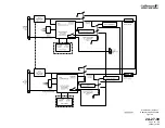
(See Figure 12.)
The rudder actuator is a dual tandem actuator consisting of two pistons
secured to a common shaft. The pistons move inside a common cylinder
divided to create two separate cylinders. One cylinder receives Flight
hydraulic system pressure while the other cylinder receives Combined
hydraulic system pressure.
Mechanical movement of the actuator input crank arm moves the servo
control valve from its neutral position. The servo control valve then directs
hydraulic pressure to one of the actuator’s two cylinders and connects
each cylinder’s opposite side to return. Movement of the actuator then
drives the rudder through an output crank, pushrod, and horn and tube
combination. When the rudder reaches the desired deflection, the servo
control valve shifts to its neutral position to lock hydraulic pressure within
the actuator, in effect preventing further surface movement.
The input cable sector and output crank are connected through a center
rear crank through a pin and slot arrangement. This pin and slot
arrangement creates 4° of differential motion between the input cable
sector and the output crank, allowing maximum servo control valve
displacement while providing a total of 3° of yaw damper authority.
D. Manual Reversion System:
During normal flight operations, the Combined and Flight hydraulic
systems each supply and maintain pressure to the rudder actuator. Loss of
system pressure from both hydraulic systems will automatically revert the
yaw flight control system to manual control. As pressure at the actuator
OPERATING MANUAL
PRODUCTION AIRCRAFT SYSTEMS
2A-27-00
Page 31
January 31/02
Revision 6
Summary of Contents for IV
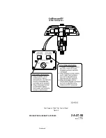
Page 17: ...Pitch Trim Controls Figure 5 OPERATING MANUAL 2A 27 00 Page 21 22 January 31 02 ...
Page 32: ...Rudder Pedals Forward Linkage Figure 13 OPERATING MANUAL 2A 27 00 Page 39 40 January 31 02 ...
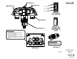
Page 50: ...Flaps Simplified Block Diagram Figure 18 OPERATING MANUAL 2A 27 00 Page 61 62 January 31 02 ...

