input shaft rotation continues during flap retraction.
D. Stabilizer Actuator:
The irreversible stabilizer actuator consists of a double Acme™ screw with
a reduction gear. One end of the actuator connects to the leading edge of
the horizontal stabilizer and the other end connects to the vertical stabilizer
structure. The reduction gear reduces the input torque shaft speed of 730
RPM to an actuator screw speed of 33 RPM to remain commensurate with
the speed of flap movement. Should a malfunction, jam or failure occur, the
actuator remains in its last commanded position.
E. Stabilizer Position and Warning System:
A transmitter at the aft upper end of the stabilizer surface supplies stabilizer
position information to the FLAP / STAB position indicator on the copilot’s
skirt panel. Although power for the system is normally supplied by the
Essential 28 VDC bus, position indication remains functional down to, and
including, emergency battery operation. Horizontal stabilizer angle of
incidence and FLAP / STAB indicator position relative to flap position is
outlined in the following table:
FLAP POSITION FLAP / STAB INDICATOR STABILIZER ANGLE OF INCIDENCE
0° (UP)
UP
1° leading edge down
10°
T/O
2.2° leading edge down
20° (T/O APPR)
APP
3.2° leading edge down
39° (DOWN)
LDG
4.6° leading edge down
A limit switch below the stabilizer position transmitter provides a warning if
the stabilizer fails to move to the proper position with flap retraction. If the
stabilizer fails to reach the 1° leading edge down position with the flaps
retracted, the limit switch causes an amber FLAP/STAB FAIL caution
message to be displayed on the Crew Alerting System (CAS).
3. Controls and Indications:
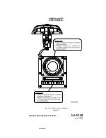
(See Figure 16 and Figure 17.)
A. Circuit Breakers (CBs):
Circuit Breaker Name:
CB Panel:
Location:
Power Source:
FLAP/STAB POS
CP
E-5
Emergency DC Bus
FLAP/STAB WARN
P
D-3
Essential DC Bus
B. Caution (Amber) Messages and Annunciations:
CAS Message:
Cause or Meaning:
STAB-FLAP FAIL
Flaps UP (0°) and stabilizer not UP.
4. Limitations:
There are no limitations established for the horizontal stabilizer system at the time
of this revision.
OPERATING MANUAL
PRODUCTION AIRCRAFT SYSTEMS
2A-27-00
Page 50
January 31/02
Revision 6
Summary of Contents for IV
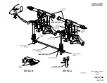
Page 17: ...Pitch Trim Controls Figure 5 OPERATING MANUAL 2A 27 00 Page 21 22 January 31 02 ...
Page 32: ...Rudder Pedals Forward Linkage Figure 13 OPERATING MANUAL 2A 27 00 Page 39 40 January 31 02 ...
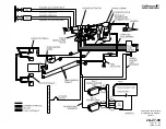
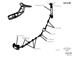
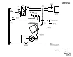
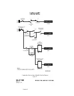
Page 50: ...Flaps Simplified Block Diagram Figure 18 OPERATING MANUAL 2A 27 00 Page 61 62 January 31 02 ...


