2A-27-20: Pitch Flight Control System
1. General Description:
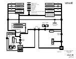
Aircraft movement about the lateral axis (pitch) is controlled by the position of the
elevators. The elevators are manually controlled, mechanically actuated and
hydraulically boosted airfoils mounted on the trailing edge of the horizontal
stabilizer. Total elevator travel ranges from 24° trailing edge up to 13° trailing edge
down.
The elevators are positioned by a tandem type hydraulic actuator. The actuator
receives hydraulic operating pressure simultaneously from both the Combined
and Flight hydraulic systems during normal operations. Loss of a single hydraulic
system has no effect on operation of the elevators, as the remaining system is
capable of maintaining actuator load capacity. In the event of total loss of
hydraulic pressure in both systems, the elevators revert to manual operation.
Manual reversion is also possible through use of a flight power shutoff valve and
its pedestal-mounted control handle.
A pitch trim system is used to position a trim tab attached to the trailing edge of
each elevator. The tabs are positioned either manually by a pedestal-mounted
control wheel or electrically by pitch trim switches on the control wheels.
An Angle-of-Attack (AOA) system provides outputs to the control column shakers,
control column pusher, approach indexers, normalized AOA display and stall
barrier system. The control column shakers provides early warning of a stall
scenario by vibrating the control column before the stall while the control column
pusher automatically initiates lowering the nose if the stall is imminent.
On CAA certified aircraft, a flight control automatic failure detection system
compares control column inputs to elevator actuator outputs. If a malfunction is
detected, the system shuts off either or both hydraulic power sources to the
affected actuator.
The pitch flight control system consists of the following subsystems, units and
components:
•
Control column system
•
Mechanical actuation system
•
Hydraulic boost system
•
Manual reversion system
•
Pitch trim system
•
Angle-of-attack / stall barrier system
•
Failure detection system (CAA aircraft only)
2. Description of Subsystems, Units and Components:
A. Control Column System:
(See Figure 7.)
The pilot’s and copilot’s control columns mount to a common transverse
torque tube supported by a bearing on each end. Moving the control
column fore and aft rotates the torque tube that, in turn, transmits the
inputs rearward through conventional mechanical linkage. Adjustable stops
on the torque tube limit control column movement to eight inches aft and
five inches forward of the neutral position.
An eddy current damper is connected to the bottom of the control column
OPERATING MANUAL
PRODUCTION AIRCRAFT SYSTEMS
2A-27-00
Page 7
January 31/02
Revision 6
Summary of Contents for IV
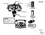
Page 17: ...Pitch Trim Controls Figure 5 OPERATING MANUAL 2A 27 00 Page 21 22 January 31 02 ...
Page 32: ...Rudder Pedals Forward Linkage Figure 13 OPERATING MANUAL 2A 27 00 Page 39 40 January 31 02 ...
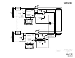
Page 50: ...Flaps Simplified Block Diagram Figure 18 OPERATING MANUAL 2A 27 00 Page 61 62 January 31 02 ...


